21
Original document - Mi-503 EN Edition: 2022-06
1
2
Note
To prevent damage, do not fit the actuator with force.
When large actuators (both single - and double acting) are used in vertical pipes, install them
with the cylinder in the pipe direction. This will result in less wear and easier maintenance.
Procedure
1. When using double acting and spring-closed actuators, ensure that the valve
is in “closed” position.
2. When using spring opened actuators, ensure that the valve is in “open”
position.
3. Lubricate the shaft and the key.
4. Fix the bracket (
➔ Fig.4-2/5) to the actuator with the aid of the bolts
(
➔ Fig.4-2/3).
5. Place the actuator with the bracket (
➔ Fig.4-2/5) in the required position
(A, B, C or D) (
➔ Fig.4-3a). on the shaft of the valve and fix the unit with the
aid of the bolts. (
➔ Fig.4-2/6).
6. Connect the clamping ring to shaft end of the valve and the actuator
(
➔ Fig.4-2/4). The clamping ring is to be mounted in such a way that its yellow
markings indicate the position of the ball segment/ball/disc. When the valve
is closed, the markings must then be offset to the direction of flow by 90°.
Clamping ring / backlash-free transmission coupling are pre-assembled on the
actuator in mounting positions A or C at delivery (
➔ Fig.4-3). For the mounting
positions B or D the clamping ring has to be turned through 90°.
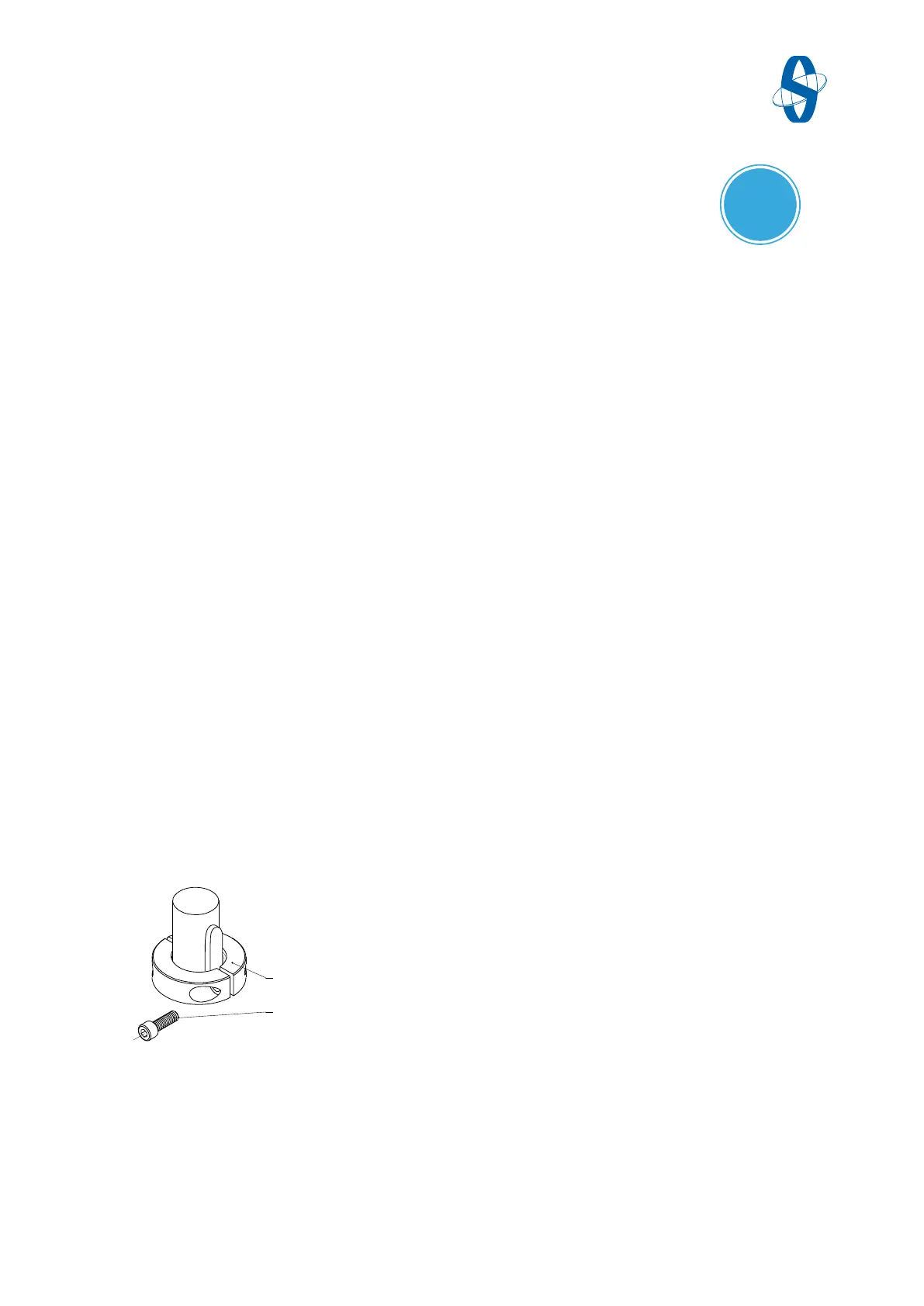
1 Clamping ring 2 Allen bolt
Fig.4-4 Mounting clamping ring
7. Tighten the bolts (➔ Fig.4-4/2) on the clamping ring (➔ F
ig.4-4/1).
8. Then set the end positions (➔ Chap.4.4).