20
Edition: 2022-06 Original document - Mi-503 EN
A
B
C
D
A, A - Standard
B,C, D - Option
7. SDIR
7. SDIR
Scale
Date
Proj.
Rev.Drawing no.
Appr.
2023-03-20
MTV DN500
A41-DA, TZID-C
Mounting position D,C
Sweden
Note
Cad Weight ±10%
Sheet
N/A
(
9
8
(
1
5
)
7. SDIR
A
A
T
h
i
s
d
o
c
u
m
e
n
t
i
s
o
u
r
p
r
o
p
e
r
t
y
a
n
d
s
h
a
ll
n
o
t
w
i
t
h
o
u
t
o
u
r
p
e
r
m
i
s
s
io
n
b
e
a
l
t
e
r
e
d
,
c
o
p
i
e
d
,
u
s
e
d
f
o
r
m
a
n
u
Rev no.
Change order no.
Date
Intr.
Appr.
Scale
Date
Proj.
Rev.Drawing no.
Appr.CopyDrawnDesign
2023-03-20
JB
U1
MTV DN500
A41-DA, TZID-C
Mounting position D,C
SÄFFLE
Sweden
WWW.SOMAS.SE
Note
Cad Weight ±10%
Sheet
1
1
/
N/A
All dimensions stated are nominal measurements with
different tolerances
General tolerance
3 mm
Further requrements for tolerance contact Somas
Acutator & Positioner mounting
position
Actuator (A, ) Positioner ( ,A)
A A
B B
C C
D D
(A,A)(B,B)(C,C)(D,D)
FLOW
Showing a general view of actuator and positioners mounting position.
(
9
8
)
(
1
5
)
Rev no.
Change order no.
Date
Intr.
Appr.
E
Scale
Date
Proj.
Rev.Drawing no.
Appr.CopyDrawnDesign
2023-03-20
JB
U1
MTV DN500
A41-DA, TZID-C
Mounting position D,C
SÄFFLE
Sweden
WWW.SOMAS.SE
Note
Cad Weight ±10%
Sheet
1
1
/
N/A
All dimensions stated are nominal measurements with
different tolerances
General tolerance
3 mm
Further requrements for tolerance contact Somas
Acutator & Positioner mounting
position
Actuator (A, ) Positioner ( ,A)
A A
B B
C C
D D
(A,A)
FLOW
(114) (186)
(
9
8
)
(
1
5
)
E
Scale
Date
Proj.
Rev.Drawing no.
Appr.CopyDrawnDesign
2023-03-20
JB
U1
MTV DN500
A41-DA, TZID-C
Mounting position D,C
SÄFFLE
Sweden
WWW.SOMAS.SE
Note
Cad Weight ±10%
Sheet
1
1
/
N/A
ons stated are nominal measurements with
olerances
olerance
3 mm
equrements for tolerance contact Somas
& Positioner mounting
position
(A, ) Positioner ( ,A)
A
B
C
D
DISC
OPEN
DISC
OPEN
FLOW
(114) (186)
(
9
8
)
(
1
5
)
ELECTRIC
CONNECTION
PNEUMATIC
CONNECTION
FLOW
(A,D)
PNEUMATIC
CONNECTION
ELECTRIC
ECTION
DISC
OPEN
DISC
OPEN
FLOW
(186)
(
9
8
)
(
1
5
)
ELECTRIC
CONNECTION
PNEUMATIC
CONNECTION
7. SDIR
7. SDIR
7. SDIR
A
D
D
7. SDIR
7. SDIR
7. SDIR
7. SDIR
7. SDIR
T
h
i
s
d
o
c
u
m
e
n
t
i
s
o
u
r
p
r
o
p
e
r
t
y
a
n
d
s
h
a
ll
n
o
t
w
i
t
h
o
u
t
o
u
r
p
e
r
m
i
s
s
io
n
b
e
a
l
t
e
r
e
d
,
c
o
p
i
e
d
,
u
s
e
d
f
o
r
m
a
n
u
Rev no.
Change order no.
Date
Intr.
Appr.
Scale
Date
Proj.
Rev.Drawing no.
Appr.CopyDrawnDesign
2023-03-20
JB
U1
MTV DN500
A41-DA, TZID-C
Mounting position D,C
SÄFFLE
Sweden
WWW.SOMAS.SE
Note
Cad Weight ±10%
Sheet
1
1
/
N/A
All dimensions stated are nominal measurements with
different tolerances
General tolerance
3 mm
Further requrements for tolerance contact Somas
Acutator & Positioner mounting
position
Actuator (A, ) Positioner ( ,A)
A A
B B
C C
D D
(A,A)(B,B)(C,C)(D,D)
FLOW
Showing a general view of actuator and positioners mounting position.
(
9
8
)
(
1
5
)
Rev no.
Change order no.
Date
Intr.
Appr.
E
Scale
Date
Proj.
Rev.Drawing no.
Appr.CopyDrawnDesign
2023-03-20
JB
U1
MTV DN500
A41-DA, TZID-C
Mounting position D,C
SÄFFLE
Sweden
WWW.SOMAS.SE
Note
Cad Weight ±10%
Sheet
1
1
/
N/A
All dimensions stated are nominal measurements with
different tolerances
General tolerance
3 mm
Further requrements for tolerance contact Somas
Acutator & Positioner mounting
position
Actuator (A, ) Positioner ( ,A)
A A
B B
C C
D D
(A,A)
FLOW
(114) (186)
(
9
8
)
(
1
5
)
B
E
Scale
Date
Proj.
Rev.Drawing no.
Appr.CopyDrawnDesign
2023-03-20
JB
U1
MTV DN500
A41-DA, TZID-C
Mounting position D,C
SÄFFLE
Sweden
WWW.SOMAS.SE
Note
Cad Weight ±10%
Sheet
1
1
/
N/A
ons stated are nominal measurements with
olerances
olerance
3 mm
equrements for tolerance contact Somas
& Positioner mounting
position
(A, ) Positioner ( ,A)
A
B
C
D
DISC
OPEN
DISC
OPEN
FLOW
(114) (186)
(
9
8
)
(
1
5
)
ELECTRIC
CONNECTION
PNEUMATIC
CONNECTION
FLOW
(A,D)
PNEUMATIC
CONNECTION
ELECTRIC
ECTION
7. SDIR
DISC
OPEN
DISC
OPEN
FLOW
(186)
(
9
8
)
(
1
5
)
ELECTRIC
CONNECTION
PNEUMATIC
CONNECTION
7. SDIR
7. SDIR
A, B
A
B
7. SDIR
T
h
i
s
d
o
c
u
m
e
n
t
i
s
o
u
r
p
r
o
p
e
r
t
y
a
n
d
s
h
a
ll
n
o
t
w
i
t
h
o
u
t
o
u
r
p
e
r
m
i
s
s
io
n
b
e
a
l
t
e
r
e
d
,
c
o
p
i
e
d
,
u
s
e
d
f
o
r
m
a
n
u
Rev no.
Change order no.
Date
Intr.
Appr.
Scale
Date
Proj.
Rev.Drawing no.
Appr.CopyDrawnDesign
2023-03-20
JB
U1
MTV DN500
A41-DA, TZID-C
Mounting position D,C
SÄFFLE
Sweden
WWW.SOMAS.SE
Note
Cad Weight ±10%
Sheet
1
1
/
N/A
All dimensions stated are nominal measurements with
different tolerances
General tolerance
3 mm
Further requrements for tolerance contact Somas
Acutator & Positioner mounting
position
Actuator (A, ) Positioner ( ,A)
A A
B B
C C
D D
(A,A)(B,B)(C,C)(D,D)
FLOW
Showing a general view of actuator and positioners mounting position.
(
9
8
)
(
1
5
)
Rev no.
Change order no.
Date
Intr.
Appr.
E
Scale
Date
Proj.
Rev.Drawing no.
Appr.CopyDrawnDesign
2023-03-20
JB
U1
MTV DN500
A41-DA, TZID-C
Mounting position D,C
SÄFFLE
Sweden
WWW.SOMAS.SE
Note
Cad Weight ±10%
Sheet
1
1
/
N/A
All dimensions stated are nominal measurements with
different tolerances
General tolerance
3 mm
Further requrements for tolerance contact Somas
Acutator & Positioner mounting
position
Actuator (A, ) Positioner ( ,A)
A A
B B
C C
D D
(A,A)
FLOW
(114) (186)
(
9
8
)
(
1
5
)
7. SDIR
E
Scale
Date
Proj.
Rev.Drawing no.
Appr.CopyDrawnDesign
2023-03-20
JB
U1
MTV DN500
A41-DA, TZID-C
Mounting position D,C
SÄFFLE
Sweden
WWW.SOMAS.SE
Note
Cad Weight ±10%
Sheet
1
1
/
N/A
ons stated are nominal measurements with
olerances
olerance
3 mm
equrements for tolerance contact Somas
& Positioner mounting
position
(A, ) Positioner ( ,A)
A
B
C
D
DISC
OPEN
DISC
OPEN
FLOW
(114) (186)
(
9
8
)
(
1
5
)
ELECTRIC
CONNECTION
PNEUMATIC
CONNECTION
FLOW
(A,D)
PNEUMATIC
CONNECTION
ELECTRIC
ECTION
C
DISC
OPEN
DISC
OPEN
FLOW
(186)
(
9
8
)
(
1
5
)
ELECTRIC
CONNECTION
PNEUMATIC
CONNECTION
7. SDIR
7. SDIR
7. SDIR
A, A
A, B
A, C
A, D
A
A
C
7. SDIR
7. SDIR
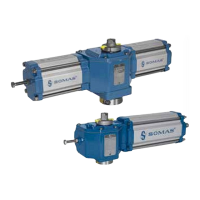
4.2.1 Installing position of the Actuator and the Positioner
Fig.4-3a Mounting positions of the Actuator
Installation position A, A (→ Fig. 4-3a) - perpendicular
to the pipeline is the standard mounting for both Actuators
and Positioners. Mounting positions B, C, D for Actuator
(→ Fig. 4-3a) and the Positioner → Fig. 4-3ab) can be selected
depending on the installation option.
The Valve and Actuators mounting position
relative the horizontal line. A mounting position with the
Valve shaft pointing upwards (vertical) is often considered to
be standard. If the media contains sticky or other difficult
impurities, that tend to collect at the bottom of the pipe, it is
advised to mount the valve with an angle of vertical.
Fig.4-3ab Mounting positions of the Positioner
In this way it is avoided that the impurities collect and
eventually clog and glue the bottom bearing of the valve shaft.
Fig.4-3b Mounting position
When large actuators (both single - and double acting) are used in vertical pipes, install them with
the cylinder in the pipe direction. This will result in less wear and easier maintenance. (
➔ Fig.4-3b).