Remove the wiring cover to access the connection plate :
1. Remove the wiring cover by unscrewing the 4
captive screws.
2. Select the input for the supply. Fix the gland
to the bottom or using the supplementary
knock-out on the side.
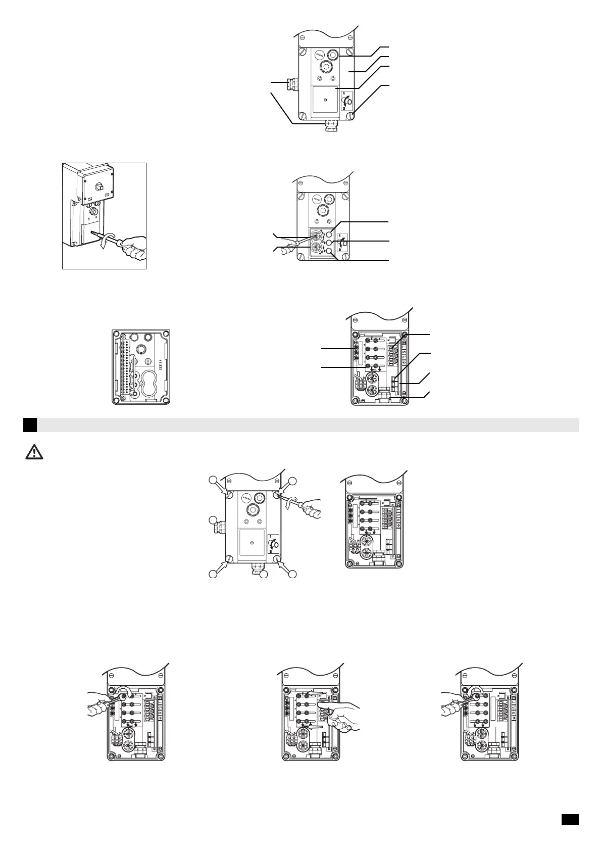
When delivered, the SOMFY COMPACT motor is set for 400 V
Select the correct supply voltage with the aid of the connection plate (230V-400V) :
To switch to 230V three-phase
Connect the power supply to the terminal. It is necessary that the cable goes through the cable glands which are located on the bottom or on the sides of the electrical
box. CABLE SIZE : MINI 1,5mm2 (3 cores and earth). Openings located on the covering cap are exclusively intended for a control circuit with a Low Safety Voltage of 24
V.
Spare fuse •
Connection plate 230V / 400V •
• Terminal plug power
• fuse
• Printed circuit with low safety
voltage 24V
• Cable gland to fix
• Slightly unscrew the 8 nuts
on the connection plate
• Retighten the 8 nuts of the connection plate• Move the connection plate to the left and
line up 230 V arrow with the lower mark
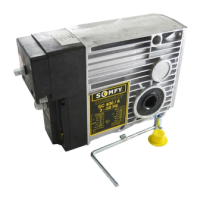
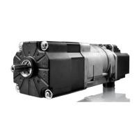
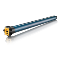
1.3 Description of front face of SOMFY COMPACT motor
On Delivery :
Remove the cap of screw-cover to access the screws :
Alternative supply connection •
Imput power 230/400V Three phases •
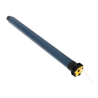
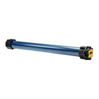
Limit switch adjusting screws
direction 1(bleu) •
Limit switch adjusting screws
direction 2 (jaune) •
• 3 imputs for 24V control circuit
• Wiring cover
• Cap of roller-cover
• 4 captive screws fixing the wiring cover
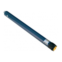
Test button (blue)
• direction1
Test button (red)
• stop
Test button (yellow)
• direction 2
Wiring cover
2/5