4
Wiring of SOMFY COMPACT
The switch must comply with annex H of standard EN 60335-1.
The switch must be located within direct sight of the driven part and away from moving parts.
The movment of the shutter may only be initiated by controls that require substained action with a key type switch or similar device (switch without locking,
which automatically returns to the stop position when the control is released).
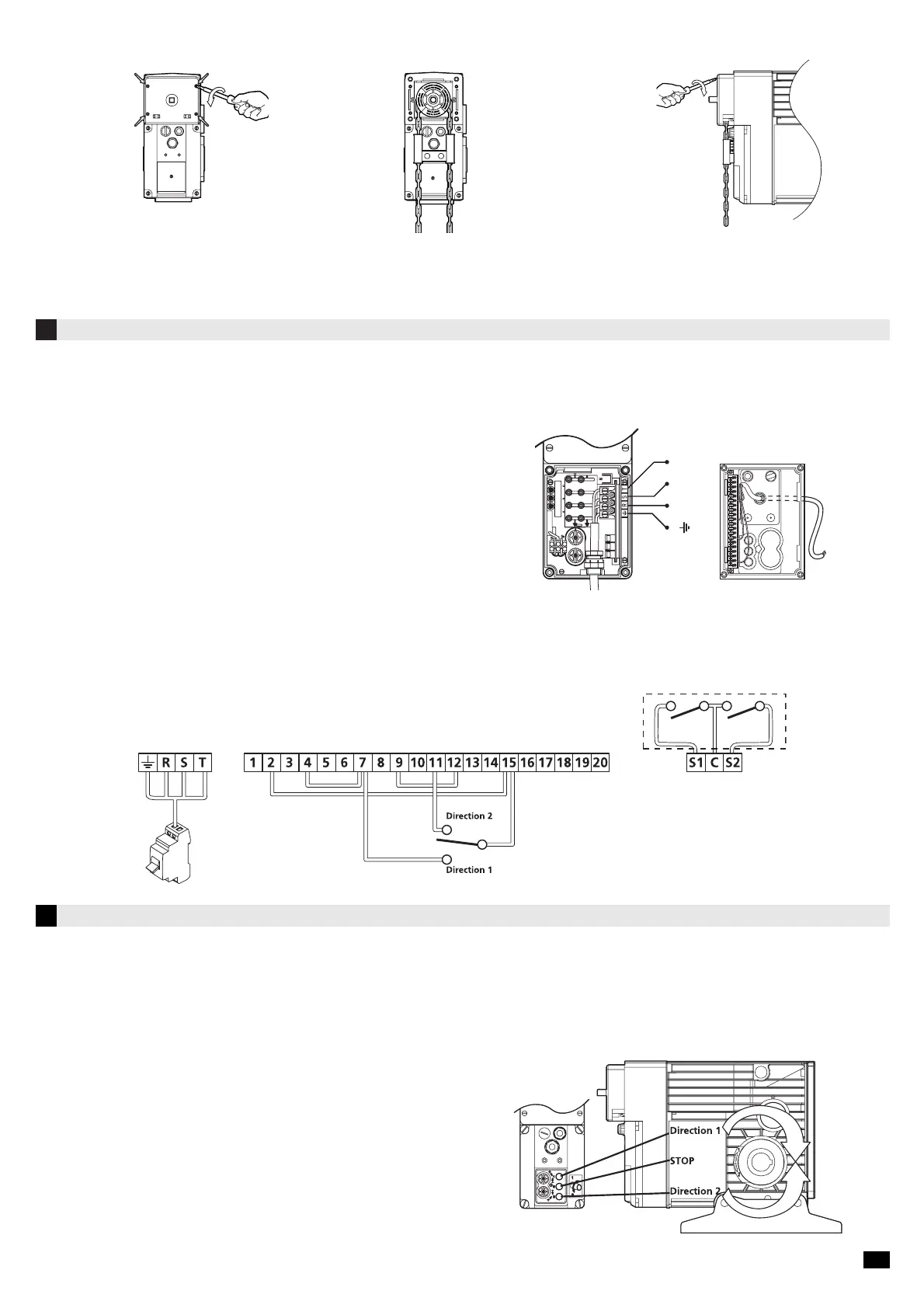
Exemple of wiring:
The cable glands for the power supply are in the wiring cover.
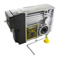
1. Remove the chain cover by unscewing the 4
screws.
2. Install the chain (réf. : 9550114) and the
chain guide (réf. :9146501).
3. Pass thes chain links in the chain guide and in
the notched wheel by introducing them in.
4. Replace the cover.
3.3 Installing the emergency chain
To connect the operating devices use the plug-in connector terminal.
Once the connections are completed, put the wiring cover in position and all the connections
are automatically made.
• Wire size: 1,5 mm
2
(Standard NF C 15-100)
• Length of bare wire : 8 mm
Wires must only go through the cable glands located on the cover of the terminal.
Use only operating devices without a supply (volt-free contact).
Any modification of the internal electrical circuit of the operator results in the cancellation of all warranties.
Electrical connection diagram :
Terminal auxiliary
contacts
5
End limit adjustment
Power supply wiring Command wiring
5.1. Checking the direction of rotation
- Once the power supply is connected, replace the wiring cover. Ensure that it is presented parallel to its location. Press in the cover.
The connector plugs in automatically on the electronic card. Finally, retighten the 4 screws.
- Switch on the installation.
- Push the upper test button (blue buton) ref. “Direction 1”. The output shaft must rotate in the direction of the arrow “ Direction 1”.
- Repeat the operation in “Direction 2”(yellow button).
- If the output shaft is rotating in the opposite direction to that which is required :
- immediately release the switch,
- switch off the supply,
- iinterchange 2 phases either on the power supply line or on the terminal box
(RST),
- switch the machine on and check the rotation direction.
Internal motor diagram
Terminal Wiring cover Terminal
4/5