EN
LS 40
4 Copyright
©
2021 SOMFY ACTIVITES SA, Société Anonyme. All rights reserved.
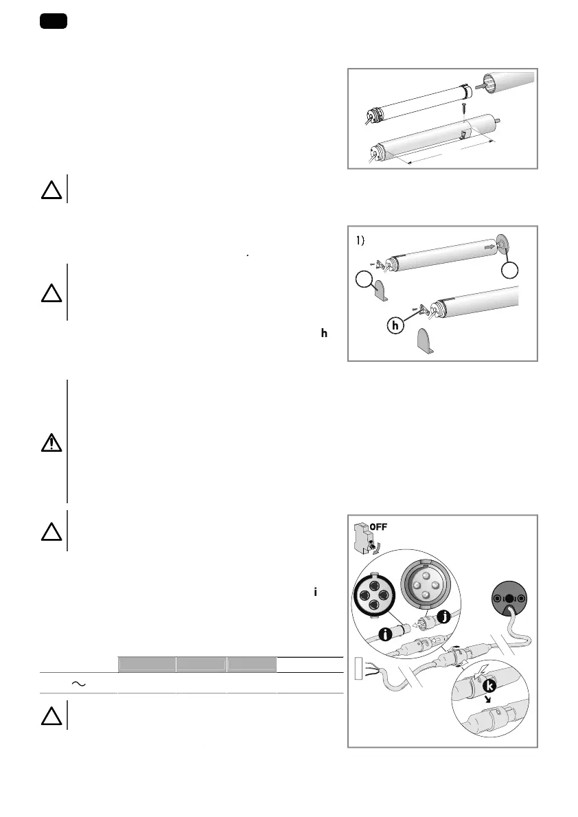
.1.
. Drive/tu
e assem
l
1) S
i
e t
e
rive into t
e win
in
tu
e.
For win
in
tu
es wit
a smoot
interior, position t
e
cut notch on the crown
2
The drive wheel must be locked in place to prevent an
ovement in the windin
tube: This can be achieved b
astenin
the windin
tube to the drive wheel usin
4
self-tappin
screws, Ø 5 mm, or 4 steel pop rivets, Ø 4.8
m, placed between 5 mm and 15 mm from the oute
ed
e of the drive wheel, re
ardless of the windin
tube.
ttentio
The screws or pop rivets must only be
astened onto the drive wheel and not on the drive
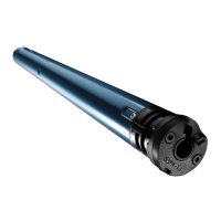
2.1.4. Installing the drive/tube assembl
1) Install and fi x the drive/tube assembl
onto the end
r
k
t
n
nt
th
riv
r
k
t
ttent
Ensure that the drive/tube assembl
is secured onto
the end bracket. This o
eration
revents the drive/tube
assembly
rom comin
out o
the end bracket mountin
.
2
Depending on the type of bracket,
t the stop ring
n
place.
WIRIN
rec
ut
• Cables which pass through a metal wall must be protected and isolated using a sheath o
l
v
Attac
ca
es to prevent any contact wit
movin
parts.
• I
the drive is used outdoors, and i
the power supply cable is a type H05 VVF cable, the cable
should be installed in a UV-resistant duct, e.
. under a
land.
The drive cable cannot be removed. I
it is damaged, return the drive to the A
ter-Sales
de
artment.
• Always make a loop in the power supply cable to prevent water enterin
the drive
ttent
Leave t
e
rive power supp
y ca
e accessi
e: it must
e possi
e to rep
ace it easi
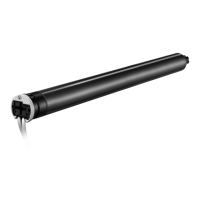
• Switch o
the power supply.
• In the case o
using an extension cable with
ast
connector plug the extension cable with
emale
ast
connector to the motor extension cable with male
ast connector.
• Connect the drive according to the in
ormation in the
table below
Neutral
N
Live
L1
Live
L2
230 V
ue
row
B
ac
ot connecte
ttentio
D
n
t
wit
• Make sure that the clip
is correctly positioned to
ensure closure
)
2
2
N
L1
L2
5160812A_LS40 ILC_8lgs.pdf 4 9/8/2021 5:12:42 PM