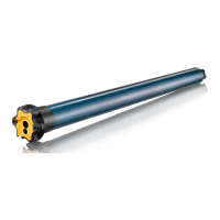
LS 40
EN
3Copyright
©
2021 SOMFY ACTIVITES SA, Société Anonyme. All rights reserved.
1.
LIABILIT
Be
ore installin
and usin
the drive, please read these instructions care
ully. In addition to the
instructions provi
e
in t
is
ui
e, p
ease a
so comp
y wit
t
e instructions set out in t
e enc
ose
Sa
et
instructions document.
The drive must be installed by a home motorisation and automation pro
essional, in accordance with
Somfy’s instructions and the applicable re
ulations in the country of installation.
Any operation o
the drive outside the sphere o
application described above is prohibited. Such
operation shall exclude Somfy from all liability and invalidate the Somfy warranty, as will any failure
to comp
y wit
t
e instructions given
erein an
in t
e enc
ose
Safet
instructions
ocument.
Aer installing the drive, the installer must inform his customers of the operating and maintenance
conditions for the drive and must pass the operating and maintenance instructions on to them, as
well as the enclosed Safet
instructions document. Any Aer-Sales Service operation on the drive
re
uires intervention by a home motorisation and automation professional
Should any doubt arise during installation of the drive or for additional information, consult a Somf
contact or visit www.somfy.com.
INSTALLATIO
recaut
o
Th
in
tr
ti
n
r
for the home motorisation and automation professional
installin
the drive.
Comply with current standards and le
islation in the country o
installation
ttentio
Never
rop,
noc
or puncture t
e
rive or immerse it in
iqui
Install an individual control point
or each drive.
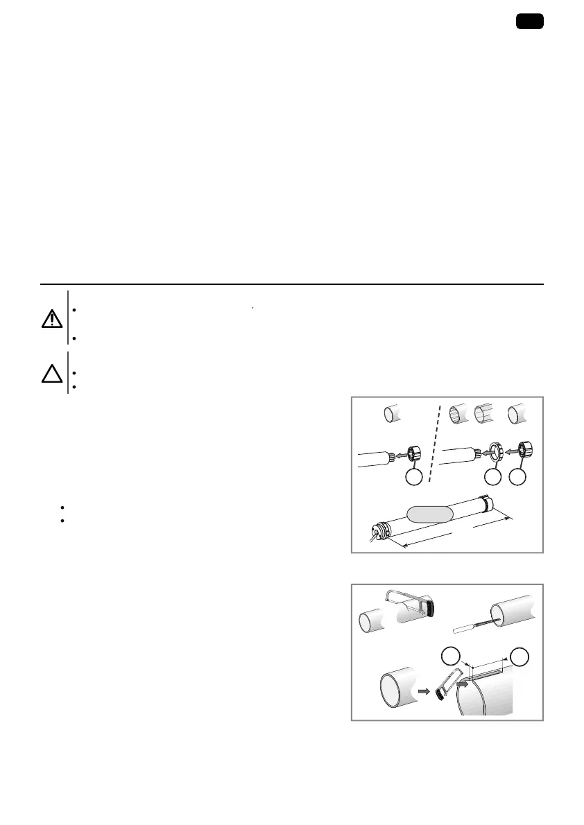
.1
A
EMBL
2.1.1
Preparin
the driv
Check that the inner diameter of the motorized product
s tube is
reater t
an 37 mm
1
Fit the accessories required to inte
rate the drive into the
win
in
tu
e:
Eith
r
t th
riv
wh
l a
n th
riv
r
t th
r
wn
n
th
riv
wh
l
n th
riv
2
Measure the length
) between the inner edge o
the
drive head and the rim o
the drive wheel.
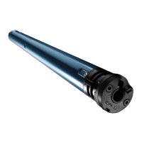
.1.
Preparing the tu
1
Cut the winding tube to the required length, depending on
the motorised
roduct.
2
Deburr the winding tube and remove the swarf.
3
For win
ing tu
es w
ic
are smoot
insi
e, cut a notc
with the following measurements: d = 7mm, e = 10 mm
=
2
>
7 mm
=
7 mm
3
1
2
5160812A_LS40 ILC_8lgs.pdf 3 9/8/2021 5:12:41 PM