Type 8221, 8212, 8142 & 8091 HPT
Type 8182 HPT Modems
HPT Variants
UM-8142
Issue B Rev 1
Section 4 – Installation and Deployment 24
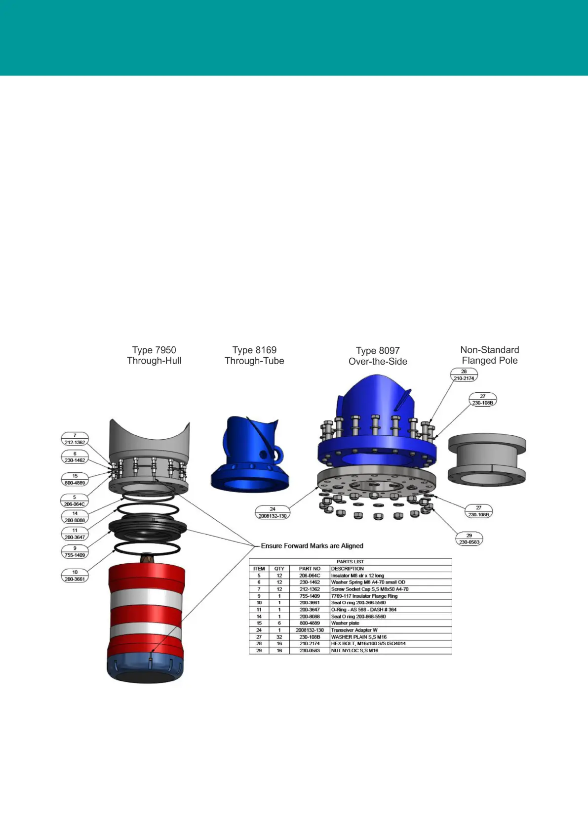
4.4.2.2 Type 8097 Over-The-Side Deployment Pole
The Type 8097 Over-the-Side Deployment Pole is supplied with a transceiver mounting flange. The
Type 8142/8182 (and variants) must be mounted using the 6G Transceiver Installation Kit (part
number 641-0197). When assembled, the transceiver and adaptor flange are bolted directly to the
lower flange of the arm assembly using 16 x M16 bolts, nuts and washers.
4.4.2.3 Type 8169 Through-Tube Deployment Pole
A 6G Transceiver Installation Kit (part number 641-0197) must be used when installing the
transceiver on a Through-Tube deployment pole. The kit contains fixings, O-rings and an isolation
flange.
4.4.2.4 Non-Standard Flanged Pole
The type 8142/8182 (and variants) USBL Transceiver can be mounted to any non-standard flanged
pole with the use of an adaptor flange. The adaptor flange must have 10.5 mm diameter equally
spaced on a 210 mm PCD. The flange must have an internal diameter of 155 mm.
A 6G Transceiver Installation Kit (part number 641-0197) must be used when installing the
transceiver on a non-standard pole. The kit contains fixings, O-rings and an isolation flange.
Figure 4-7 Type 8142/8182 Standard Mounting Methods