Lodestar Hardware
Manual
Document Ref: UM-8084-
Issue: A– Rev
© Sonardyne International Limited 201
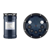
A 14-way female Lemo port that allows
connection of a PC to communicate with
the
Lodestar for configuration or data
logging purposes. DC power for the unit
may be connected here (24 / 8 V
nominal).
IMPORTANT: The console port
connection uses a channel select line
to specify RS232 (default) or RS485.
–
Connect Channel select to ground if
you are using RS232.
– Leave Channel select disconnected if
RS232_1
RS485/
RS232_2
a
Two 12-way female Lemo ports that allow
serial data connection between the
Lodestar and external equipment. These
ports are both available to:
• transmit measurements from the
Lodestar to receiving equipment
•
receive aiding information from
external sources, for example a
GPS receiver
• send or receive a trigger signal
Ports
A 10-way female Lemo port that allows
direct serial connection between Lodestar
and Sonardyne acoustic transceivers or
other external instruments.
These ports are also both available to:
•
transmit measurements from
Lodestar to receiving equipment
•
receive aiding information from
external sources, for example a
GPS receiver.
• send or receive a trigger signal
A 3-way male inlet port that accepts
electrical power from an external mains
electrical source. This port accepts 110 /
230 V AC at 50 / 60 Hz.
Lodestar draws a maximum 20watts from
the external power. There is a 500mA(T)
fuse in line with
supply. The fuse is accessible without
A 100BaseT Ethernet port.
a
When using Lodestar to supply NMEA outputs to multiple listening devices, use a two-wire shielded
twisted pair. See section 5.7 beginning on page 31 for information. The RS485 differential line consists
of two pins – ‘A’ and ‘B’ as defined in the NMEA standard:
‘A’ (TxD– / RxD-), or the inverting pin, is negative (compared to B) when the line is idle (data is 1)
‘B’ (TxD+ / RxD+), or the non-inverting pin, is positive (compared to A) when the line is idle (data is 1)