EasyManua.ls Logo

Sony AVD-K150B User Manual

Sony AVD-K150B
92 pages
To Next Page IconTo Next Page
Page #1 background imageLoading...
Page #1 background image
SERVICE MANUAL
Sony Corporation
Home Audio Company
Published by Sony Engineering Corporation
AEP Model
AVD-K150B/K150E/K150N/K150R
UK Model
AVD-K150G
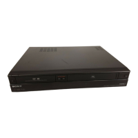
DVD/VCR RECEIVER
9-877-959-01
2004F1678-1
© 2004.06
Ver 1.0 2004.06
SPECIFICATIONS
AVD-K150B/K150E/K150G/
K150N/K150R
General
Power requirements AC 230 V , 50/60 Hz
Power consumption 74W
Dimensions (approx.) 430 x 98 x 386 mm
7
/
8
x 15
1
/
4
inches) (W x H x D)
Mass (approx.) 6.5 kg (14 lb 6 oz)
Operating temperature 5
°
C to 35
°
C (41
°
F to 95
°
F)
Operating humidity 5 % to 90 %
DVD Section
Laser Semiconductor laser (Wavelength
Signal system PAL
Frequency response DVD (PCM 48 kHz): 10 Hz to 22 kHz
CD: 10 Hz to 20 kHz
Signal-to-noise ratio More than 80 dB (ANALOG OUT
connectors only)
Harmonic distortion Less than 0.05%
VIDEO Section
Head system 4 heads helical scan azimuth system
Television system PAL B/G colour system (150E)
PAL B/G, SECAM L colour system (150B)
PAL B/G, SECAM D/K colour system (150N)
PAL (B/G, I/I), SECAM D/K colour system (150R)
PAL I colour system (150G)
Recording format PAL
(17 x 3
DVD: 650nm, CD: 780nm)
Tape speed PAL/MESECAM; 23.39 mm/s (SP),
16.69 mm/s (LP)
Maximum recording time SP: 4 hour (E-240 tape), LP: 8 hour
Rewind time About 180 seconds (E-180 tape)
Input level VIDEO: 1.0 V(p-p), 75 ohms, unbalanced
AUDIO: -6.0 dBm, more than 10 kohms (SCART)
-6.0 dBm, more than 47 kohms (RCA)
DIGITAL AUDIO IN: Optical connector x 1
Output level VIDEO: 1.0 V(p-p), 75 ohms, unbalanced
(E-240 tape)
FM Tuner
Tuning Range
87.5 - 108.0 MHz (ALL MODEL)
65 - 74 MHz (150R)
Intermediate Frequency 10.7 MHz
AM Tuner
Tuning Range 522 - 1,611 kHz
Intermediate Frequency 450 kHz
Amplifier Section
Stereo mode 70W + 70W (6 at 1 kHz, THD 10 %)
Surround mode Front: 70W/ch (6 at 1 kHz, THD 10 %)
Center*: 70W (6 at 1 kHz, THD 10 %)
Surround*: 70W/ch (6 at 1 kHz, THD 10 %)
Subwoofer*: 100W (4 at 30 Hz, THD 10 %)
*
Depending on the sound mode settings and the source,
Inputs AV 2, AV 3, OPTICAL IN (AV3 OPT)
there may be no sound output.
Design and specifications are subject to change without notice.
AVD-K150B/K150E/K150G/K150N/K150R is the
Amplifier, DVD/VIDEO player and tuner section
in DAV-D150B/D150E/D150G/D150N/D150R.
• Manufactured under license from Dolby Laboratories. "Dolby", "Pro
Logic", and the double-D symbol are trademarks of Dolby Laboratories.
Confidential unpublished works. Copyright 1992 -1997 Dolby
Laboratories. All rights reserved.
• DTS and DTS Digital Surround are registered trademarks of Digital
Theater Systems, Inc.
Model Name Using Similar Mechanism NEW
DVD Mechanism Type DP-7C
Optical Pick-up Name PVR-502W
VCR Mechanism Type D35 (N)
Table of Contents

Questions and Answers:

Sony AVD-K150B Specifications

General IconGeneral
BrandSony
ModelAVD-K150B
CategoryDVD VCR Combo
LanguageEnglish

Summary

Specifications Overview

DVD/VCR Mechanism and Recording Details

Covers mechanism types, pick-up names, and recording time specifications.

Signal, Input/Output, and Tuner Specifications

Details frequency response, signal-to-noise, tuner ranges, and I/O levels.

Amplifier and Video System Specifications

Covers amplifier power, surround modes, inputs, video system, and tape speed.

Safety and Handling Precautions

Laser and Handling Safety Measures

Covers Class 1 Laser Product, optical pick-up, and general handling safety.

Repair and Component Safety Precautions

Precautions for chip components, flexible circuits, unleaded solder, and critical parts.

Service Positions for Mechanisms

DVD Mechanism Deck Service Position

Setup procedure for inspecting the DVD mechanism deck.

Video Mechanism Deck Service Position

Procedure for operation check of the video mechanism deck.

Front Panel Controls and Indicators

Power, Volume, and Media Controls

Controls for powering the unit, adjusting volume, and selecting media.

Playback, Recording, and Tuning Operations

Buttons for controlling playback, recording, tuning, and channel selection.

Display Window and Remote Sensor

Information on the unit's status display and remote sensor location.

Display Window Indicators

Playback, Speed, and Repeat Indicators

Displays for playback modes, speed, and repeat settings.

Signal, Mode, and Source Indicators

Indicators for broadcast signals, audio modes, and input sources.

Remote Control Functions and Operations

Source, Tuning, and Input Selection Controls

Buttons for selecting sources, tuning stations, and inputs.

Playback, Program, and Recording Controls

Buttons for controlling playback, recording, and programming functions.

Menu Navigation and DVD-Specific Functions

Controls for accessing menus and DVD-specific features.

Additional Remote Control Features

Buttons for RDS, subtitle, audio language, and other remote functions.

Rear Panel Connections and Setup

Antenna and Speaker Terminal Connections

Terminals for connecting FM/AM antennas and speaker systems.

AV and Digital Audio Input Ports

Ports for connecting AV devices and digital audio sources.

Power Input and Antenna Output

AC power input and antenna output connections.

Connector Handling and Battery Installation

Precautions for dust caps, connectors, and remote control battery installation.

External Device Connectivity

AV Connections to Television

Using SCART lead for AV connection to a television.

RF Connections to Television

Using aerial cable for RF connection to a television.

Decoder Connection for Encrypted Signals

Connecting a decoder for encrypted television signals.

Additional Connectivity Options

Radio Antenna and Connection Details

Connecting AM loop and FM wire antennas for radio reception.

Digital Device Optical Audio Connection

Connecting digital devices via optical audio cable.

Accessory Audio/Video Connections

Connecting external audio/video devices via AV3 IN ports.

Speaker Setup and Configuration

Speaker Connection Guidelines

Instructions for matching speaker cords to appropriate terminals.

Speaker Placement Recommendations

Guidelines for positioning speakers for optimal surround sound.

Ferrite Core and Foot Pad Installation

Instructions for attaching ferrite cores and foot pads to speakers.

Disassembly Procedures

Front Panel and Cover Removal

Steps for removing the front panel and cover assembly.

Component Disassembly Steps

Display and Key Board Removal

Steps for removing the display and key board assemblies.

Video Mechanism Deck Removal

Steps for removing the video mechanism deck assembly.

Component Disassembly Steps

DVD Mechanism Deck Removal

Steps for removing the DVD mechanism deck assembly.

SMPS Board Removal

Steps for removing the SMPS (Switch Mode Power Supply) board.

Component Disassembly Steps

VCR Board Removal

Steps for removing the VCR main board assembly.

DVD & AMP Board Removal

Steps for removing the DVD & AMP main board assembly.

VCR Section Electrical Adjustments

PG Adjustment Procedure and Waveforms

Steps for PG adjustment with test equipment and waveform analysis.

Electrical Troubleshooting - Power (SMPS) Circuit

Troubleshooting No 5.3VA Power Supply

Flowchart for diagnosing 5.3VA power supply issues.

Troubleshooting No 12VA Power Supply

Flowchart for diagnosing 12VA power supply issues.

Troubleshooting No 5.0V Power Supply

Flowchart for diagnosing 5.0V power supply issues.

Electrical Troubleshooting - Power Voltages

Troubleshooting No 5V (DVD) Supply

Flowchart for diagnosing 5V supply issues specific to the DVD section.

Troubleshooting No 33V (TUNER) Supply

Flowchart for diagnosing 33V supply issues specific to the tuner section.

Electrical Troubleshooting - System/Key Circuit

Troubleshooting Auto Stop Function

Flowchart for diagnosing auto stop mechanism failures.

Troubleshooting Cassette Loading Issues

Flowchart for diagnosing unstable tape loading problems.

Electrical Troubleshooting - Servo Circuit

Troubleshooting Unstable Video (PB Mode)

Flowchart for diagnosing unstable video signal in playback mode.

Troubleshooting Drum Motor Not Running

Flowchart for diagnosing drum motor operation failures.

Electrical Troubleshooting - Servo Circuit

Troubleshooting Capstan Motor Not Running

Flowchart for diagnosing capstan motor operation failures.

Electrical Troubleshooting - Keypad Issues

Troubleshooting Keypad Not Working

Flowchart for diagnosing keypad input or function failures.

Electrical Troubleshooting - Y/C Circuit

Troubleshooting No Video in EE Mode

Flowchart for diagnosing no video signal in EE mode.

Electrical Troubleshooting - Y/C Circuit

Troubleshooting Luminance Signal Loss (PB Mode)

Flowchart for diagnosing loss of luminance signal in playback mode.

Electrical Troubleshooting - Y/C Circuit

Troubleshooting Color Signal Loss (PB Mode)

Flowchart for diagnosing loss of color signal in playback mode.

Electrical Troubleshooting - Y/C Circuit

Troubleshooting No Video in REC Mode

Flowchart for diagnosing no video signal in recording mode.

Electrical Troubleshooting - Hi-Fi Circuit

Troubleshooting No Sound in EE Mode

Flowchart for diagnosing no audio signal in EE mode.

Electrical Troubleshooting - Hi-Fi Circuit

Troubleshooting No Sound in Hi-Fi Playback

Flowchart for diagnosing no audio during Hi-Fi playback.

Electrical Troubleshooting - Hi-Fi Circuit

Troubleshooting Hi-Fi Recording Failure

Flowchart for diagnosing Hi-Fi audio recording failures.

Electrical Troubleshooting - Tuner/IF Circuit

Troubleshooting No TV Picture

Flowchart for diagnosing no video signal appearing on the TV screen.

Electrical Troubleshooting - Tuner/IF Circuit

Troubleshooting No Sound from Tuner

Flowchart for diagnosing no audio signal from the tuner section.

DVD/AMP Section Troubleshooting Guide

System Operation Flowchart

Overall operational logic for DVD/AMP functions.

DVD/AMP Section Test and Debug Flow

Test and Debugging Procedures

Step-by-step debugging process for the DVD/AMP section.

DVD/AMP Section Troubleshooting Steps

System Initialization and Signal Checks

Verifying Flash Memory, SDRAM, and video output signals.

DVD/AMP Section Troubleshooting Steps

SLED and Optical Pickup Movement Checks

Verifying SLED movement and optical pickup focus.

DVD/AMP Section Troubleshooting Steps

Laser and Disc Reading Checks

Verifying laser operation and disc ID correctness.

Spindle Rotation and Signal Checks

Checking spindle rotation and RF/DMSO signals.

DVD/AMP Section Troubleshooting Steps

Focus and Tracking Operation Checks

Verifying optical pickup focus and tracking operation.

Disc Playback and RF Signal Checks

Confirming disc playback and RF waveform integrity.

DVD/AMP Section Troubleshooting Steps

Audio Output and DAC Data Stream Checks

Verifying audio output and DAC data stream correctness.

Audio µ-COM Circuit Troubleshooting

System Operation and Initial Checks

Verifying power, CD/DVD detection, and loading states.

Circuit and Component Troubleshooting

Troubleshooting power, oscillators, and specific IC pins.

Mechanical Adjustments Overview

Service Tools and Fixtures Required

Listing necessary tools for performing mechanical adjustments.

Alignment Tapes and Settings

Specifying alignment tapes and settings for adjustments.

Mechanism Alignment Procedures

Mechanism Position Check Procedure

Verifying mechanism position after tape ejection.

Alignment Diagram and Checks

Visual guide for alignment points and related checks.

Tape Transport Mechanism Checks

Deck Mechanism Preparation for Adjustment

Setting up the deck mechanism without a cassette tape.

Tape Transport Torque Checking

Measuring tape transport torque for various operational modes.

Guide Roller Height Adjustment

Preliminary Guide Roller Height Adjustment

Initial adjustment of guide roller height for correct tape path.

Precise Guide Roller Height Adjustment

Fine-tuning guide roller height using RF waveform.

A/C Head Adjustment Procedures

Preliminary Height and Tilt Adjustment

Initial height and tilt adjustment for A/C head alignment.

A/C Head Base and Assembly Diagrams

Visual aids illustrating A/C head base and assembly.

A/C Head and X-Value Adjustments

Tape Path Smoothness Confirmation

Checking tape path for curling or folding after adjustment.

Precise Azimuth Adjustment

Adjusting azimuth for optimal RF envelope output.

X-Value Adjustment Procedure

Adjusting X-value for VCR model compatibility.

Post-Assembly Checks and Adjustments

Drum Assembly Adjustment Procedures

Roller guide and X-value adjustments after drum replacement.

Tape Travel and Locking Time Checks

Verifying audio/RF lock and tape travel after reassembly.

Pre-Repair Checks and Maintenance

Common Faults and Inspection Points

Identifying common issues like dirt, poor S/N, and jitter.

Tape Path and Component Identification

Diagram of tape path and numbered components for reference.

Maintenance Procedures and Supplies

Maintenance Requirements and Schedules

Recommended maintenance frequency and required supplies.

Video Head and System Cleaning Steps

Steps for cleaning video heads and the tape transport system.

Lubrication Procedures

Greasing Guidelines and Points

Instructions for applying grease to mechanism parts.

Periodic Greasing Locations

Specific points requiring lubrication at 5,000-hour intervals.

Diagrams and Circuit Board Layout

Circuit Board Identification and Locations

Locations of main circuit boards within the unit.

Diagram Notation and Abbreviations

Explanation of symbols and terms used in schematics and PWB diagrams.

Block Diagrams - DVD Section

Overall DVD System Block Diagram

High-level overview of the DVD system's architecture.

Block Diagrams - DVD/Amplifier Section

DVD Amplifier Section Block Diagram

Detailed schematic of the DVD amplifier circuitry.

Block Diagrams - VCR/Panel Section

VCR System Control Block Diagram

Overview of the VCR's system controller and associated blocks.

Block Diagrams - VCR Y/C Section

VCR Y/C Processing in Playback Mode

Diagram showing Y/C signal path during playback.

VCR Y/C Processing in Record Mode

Diagram showing Y/C signal path during recording.

Block Diagrams - VCR TU/NICAM/VPS Section

TU, NICAM & A2 Block Diagram

Diagram for tuner, NICAM, and A2 sound demodulation.

VPS Block Diagram

Diagram illustrating the Video Programming System interface.

Block Diagrams - VCR Hi-Fi Section

Hi-Fi Audio Processing Block Diagram

Schematic of the Hi-Fi audio processor and inputs.

AV Switch and Modulator Diagram

Diagram showing AV switching and signal modulation.

Block Diagrams - VCR Power Section

VCR Power Supply Control Diagram

Block diagram of the VCR power supply and regulation system.

Block Diagrams - Power Supply Section

Power Supply Circuit Overview Diagram

High-level block diagram of the main power supply unit.

Printed Wiring Boards - DVD & AMP Section

DVD & AMP Board Component Layout

Component placement view of the DVD & AMP board.

Printed Wiring Boards - DVD & AMP Section

DVD & AMP Board Conductor Layout

Conductor layout view of the DVD & AMP board.

Schematic Diagrams - DVD & AMP Section

MPEG Section Schematic Diagram

Detailed schematic of the MPEG processing circuitry.

Schematic Diagrams - DVD & AMP Section

RF & Servo Section Schematic Diagram

Detailed schematic of the RF and servo control circuits.

Schematic Diagrams - DVD & AMP Section

Audio and µ-COM Section Schematic Diagram

Detailed schematic of the audio processing and microcontroller circuits.

Schematic Diagrams - DVD & AMP Section

Digital Amplifier Section Schematic Diagram

Detailed schematic of the digital amplifier stages.

Schematic Diagrams - DVD & AMP Section

PWM and CODEC Section Schematic Diagram

Detailed schematic of PWM control and codec circuitry.

Schematic Diagrams - DVD & AMP Section

Interface Section Schematic Diagram

Detailed schematic of the unit's interface connections.

Printed Wiring Boards - VCR Section

VCR Board Component Layout

Component placement view of the VCR board.

Schematic Diagrams - VCR Section

VCR System Overview Schematic Diagram

High-level schematic of the VCR system's main blocks.

Schematic Diagrams - VCR Section

AVCP/SECAM Section Schematic Diagram

Schematic for AV compatibility and SECAM signal processing.

Schematic Diagrams - VCR Section

Hi-Fi and Switch Section Schematic Diagram

Schematic for Hi-Fi audio processing and input switching.

Schematic Diagrams - VCR Section

TU, NICAM & VPS Section Schematic Diagram

Schematic for tuner, NICAM sound, and VPS data.

Schematic Diagrams - VCR Section

SCART and Switch Section Schematic Diagram

Schematic for SCART interface and signal switching.

Schematic Diagrams - VCR Section

VCR Power Supply Schematic Diagram

Schematic diagram of the VCR's power supply circuitry.

Printed Wiring Boards - Display/Key Section

Display Board Component Layout

Component placement view of the display board.

Key Board Component Layout

Component placement view of the key board.

Schematic Diagrams - Display/Key Section

Key Board Schematic Diagram

Circuit diagram detailing the keypad functions.

Display Board Schematic Diagram

Circuit diagram detailing the display board functions.

Printed Wiring Boards - SMPS Section

SMPS Board Component Layout

Component placement view of the SMPS board.

Schematic Diagrams - SMPS Section

SMPS Circuit Schematic Diagram

Detailed schematic diagram of the SMPS circuit.

Exploded Views

Front Panel Assembly Exploded View

Exploded view showing components of the front panel.

Exploded Views

Overall Unit Assembly Exploded View

Exploded view illustrating the main components of the unit.

Exploded Views - DVD Mechanism Deck

DVD Mechanism Deck Components

Exploded view listing parts of the DVD mechanism deck.

Exploded Views - Video Mechanism Deck

Video Mechanism Deck Components (Part 1)

Exploded view of video mechanism parts, first part.

Exploded Views - Video Mechanism Deck

Video Mechanism Deck Components (Part 2)

Exploded view of video mechanism parts, second part.

Exploded Views - Video Mechanism Deck

Video Mechanism Deck Components (Part 3)

Exploded view of video mechanism parts, third part.

Electrical Parts List

Display and DVD/AMP Section Parts

List of electrical components for display and DVD/AMP sections.

Electrical Parts List

Key, SMPS, and VCR Section Parts

List of electrical components for Key, SMPS, and VCR sections.

Electrical Parts List - VCR Components

VCR Transistors, Diodes, and ICs

List of VCR semiconductors including transistors, diodes, and ICs.

VCR Connectors, Switches, and Miscellaneous Parts

List of VCR connectors, switches, and miscellaneous components.

Related product manuals