SERVICE MANUAL
Sony Corporation
Home Audio Company
Published by Sony Engineering Corporation
AEP Model
AVD-K150B/K150E/K150N/K150R
UK Model
AVD-K150G
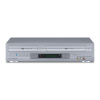
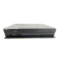
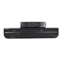
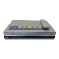
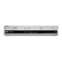
DVD/VCR RECEIVER
9-877-959-01
2004F1678-1
© 2004.06
Ver 1.0 2004.06
SPECIFICATIONS
AVD-K150B/K150E/K150G/
K150N/K150R
General
Power requirements AC 230 V , 50/60 Hz
Power consumption 74W
Dimensions (approx.) 430 x 98 x 386 mm
7
/
8
x 15
1
/
4
inches) (W x H x D)
Mass (approx.) 6.5 kg (14 lb 6 oz)
Operating temperature 5
°
C to 35
°
C (41
°
F to 95
°
F)
Operating humidity 5 % to 90 %
DVD Section
Laser Semiconductor laser (Wavelength
Signal system PAL
Frequency response DVD (PCM 48 kHz): 10 Hz to 22 kHz
CD: 10 Hz to 20 kHz
Signal-to-noise ratio More than 80 dB (ANALOG OUT
connectors only)
Harmonic distortion Less than 0.05%
VIDEO Section
Head system 4 heads helical scan azimuth system
Television system PAL B/G colour system (150E)
PAL B/G, SECAM L colour system (150B)
PAL B/G, SECAM D/K colour system (150N)
PAL (B/G, I/I), SECAM D/K colour system (150R)
PAL I colour system (150G)
Recording format PAL
(17 x 3
DVD: 650nm, CD: 780nm)
Tape speed PAL/MESECAM; 23.39 mm/s (SP),
16.69 mm/s (LP)
Maximum recording time SP: 4 hour (E-240 tape), LP: 8 hour
Rewind time About 180 seconds (E-180 tape)
Input level VIDEO: 1.0 V(p-p), 75 ohms, unbalanced
AUDIO: -6.0 dBm, more than 10 kohms (SCART)
-6.0 dBm, more than 47 kohms (RCA)
DIGITAL AUDIO IN: Optical connector x 1
Output level VIDEO: 1.0 V(p-p), 75 ohms, unbalanced
(E-240 tape)
FM Tuner
Tuning Range
87.5 - 108.0 MHz (ALL MODEL)
65 - 74 MHz (150R)
Intermediate Frequency 10.7 MHz
AM Tuner
Tuning Range 522 - 1,611 kHz
Intermediate Frequency 450 kHz
Amplifier Section
Stereo mode 70W + 70W (6 Ω at 1 kHz, THD 10 %)
Surround mode Front: 70W/ch (6 Ω at 1 kHz, THD 10 %)
Center*: 70W (6 Ω at 1 kHz, THD 10 %)
Surround*: 70W/ch (6 Ω at 1 kHz, THD 10 %)
Subwoofer*: 100W (4 Ω at 30 Hz, THD 10 %)
*
Depending on the sound mode settings and the source,
Inputs AV 2, AV 3, OPTICAL IN (AV3 OPT)
there may be no sound output.
• Design and specifications are subject to change without notice.
AVD-K150B/K150E/K150G/K150N/K150R is the
Amplifier, DVD/VIDEO player and tuner section
in DAV-D150B/D150E/D150G/D150N/D150R.
• Manufactured under license from Dolby Laboratories. "Dolby", "Pro
Logic", and the double-D symbol are trademarks of Dolby Laboratories.
Confidential unpublished works. Copyright 1992 -1997 Dolby
Laboratories. All rights reserved.
• DTS and DTS Digital Surround are registered trademarks of Digital
Theater Systems, Inc.
Model Name Using Similar Mechanism NEW
DVD Mechanism Type DP-7C
Optical Pick-up Name PVR-502W
VCR Mechanism Type D35 (N)