3-18 (E)
BKM-21D
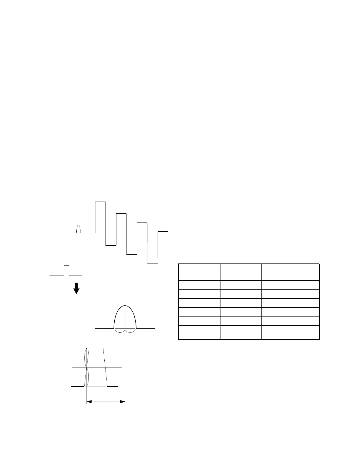
APC PB OUT
(IC325-7)
Chroma clamp
pulse (TP312)
Enlargement
APC PB OUT
Chroma clamp
pulse
Specification A = 6.0 ± 0.3 usec
a
b
A
a = b
3-3-13. PAL-D Y/C DELAY Adjustment
(BD Board)
1. Set 02 CH.
2. Read the following adjustment data at the BKM-21D
menu of the MAINTENANCE menu.
BB0 RB0 YB0 YW0
BB1 RB1 YB1 YW1
BB2 YB2
3. Set 03 CH.
4. Set the following adjustment data to the same value as
the PAL-S mode data read at step 2 at the BKM-21D
menu of the MAINTENANCE menu.
BB0 RB0
BB1 RB1
BB2
5. Take YW1, YW0, YB2, YB1, and YB0 as 5-bit binary
number (YW1 is MSB and YB0 is LSB), use the PAL-
D mode value obtained by adding 00001 (01H) to the
PAL-S mode value and set the following adjustment
data.
YB0 YW0
YB1 YW1
YB2
(Example)
PAL-S Mode PAL-D Mode
Adjustment Data Adjustment Data
YW1 1 1
YW0 0 0
YB2 0 0
YB1 0 1
YB0 1 0
Binary 10001 10001 + 00001 = 10010
(Hexadecimal) (11H) (11H + 01H = 12H)
3-3-12. PAL-D Chroma Clamp Pulse
Adjustment (BD Board)
n
The following adjustment menu is below the BKM-21D
menu of the MAINTENANCE menu.
CCP-P (CHROMA CLAMP PULSE-POSITION)
1. Input the composite PAL 100% color bar into the
VIDEO 4 input terminal.
(Full-field 0% set up)
2. Set 03 CH.
FORMAT.......... COMPOSITE PAL D
3. Connect the CH1 probe of the oscilloscope to Pin 7
of IC325 of the BD board and connect the CH2 probe
to TP312 of the BD board.
4. Adjust the CCP-P (CHROMA CLAMP PULSE-
POSITION) data so that the position A of the chroma
clamp pulse satisfies the specification.
Fig. 3-12.


 To Next Page