3-24 (E)
BKM-21D
9. Connect the oscilloscope as follows.
CH1: TP201 of BD board (Y OUT)
CH2 : TP601 of BD board (PR OUT)
EXT. TRING. : Pin
20a
of CN2 of BD board
(H SYNC)
10. Adjust the position of the oscilloscope and coincide
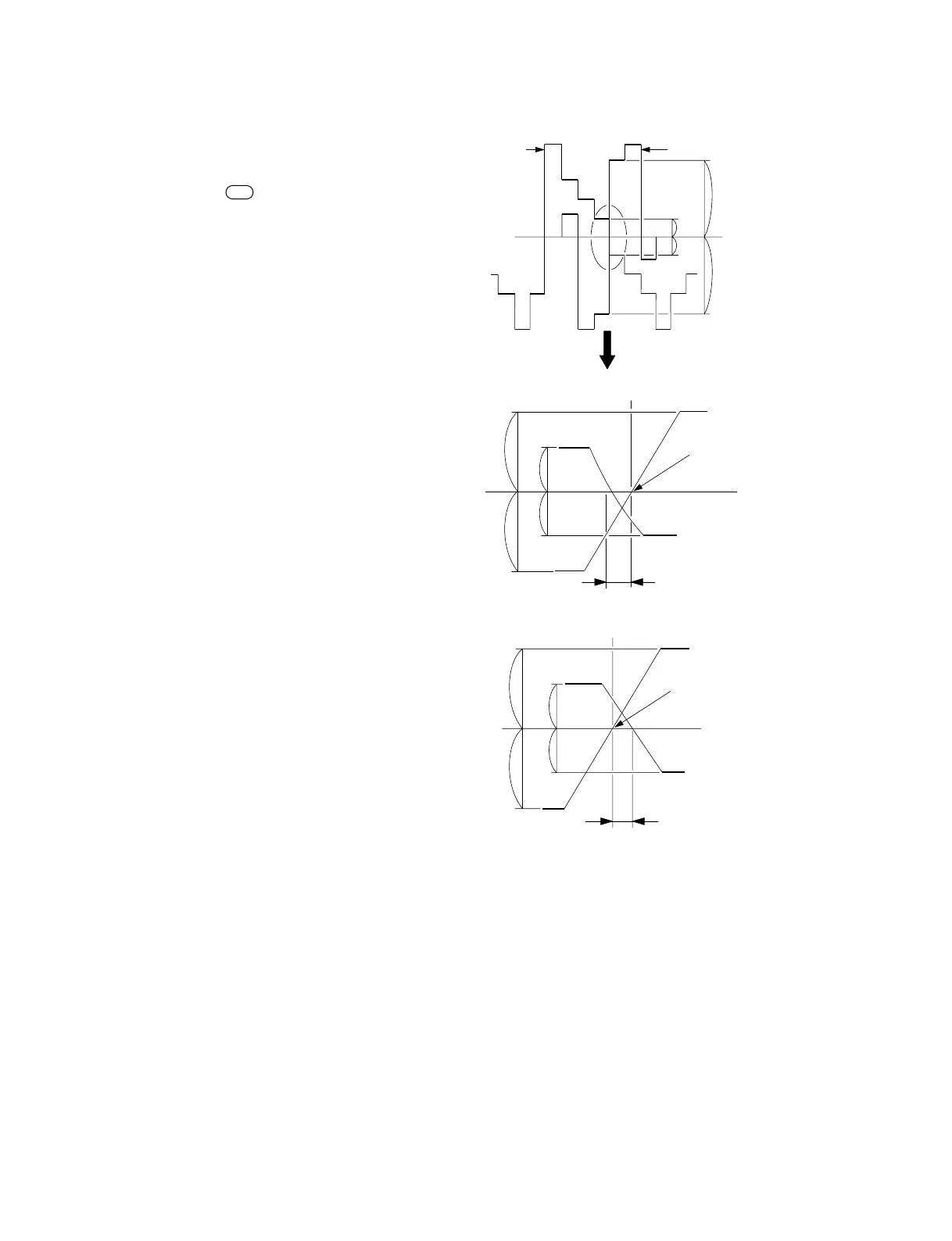
the TP201 and TP601 waveforms as shown in Fig.5-5
(1).
11. Set the oscilloscope to the delay mode and enlarge the
border between the green and magente as shown in
Fig.5-5 (2) and (3).
(Setting the oscilloscope to the EXT.TRING mode.)
12. Concide the center of the TP601 (PR OUT) waveform
to the horizontal vertical center of the oscilloscope.
13. Adjust the data as follows so that the horizontal
deviation B of the TP201 (Y OUT) waveform is within
the specification.
(If deviated to the left as shown in Fig. 5-5 (2).)
YW1 : 1 → 1 → 1
YW0 : 0 → 0 → 0
YB2 : 0 → 0 → 0
YB1 : 0 → 0 → 1
YB0 : 0 → 1 → 0
(If diviated to the right as shown in Fig. 5-5 (3).)
YW1 : 1 → 0 → 0
YW0 : 0 → 1 → 1
YB2 : 0 → 1 → 1
YB1 : 0 → 1 → 1
YB0 : 0 → 1 → 0
(1)
(2)
(3)
Fig. 5-5.
TP201
TP601
c
d
a
b
Vertical center
of the oscilloscope
Enlargement
Horizontal vertical center
of the oscilloscope
a
b
c
d
B
PR
Y
a = b
c = d
Horizontal vertical center
of the oscilloscope
a = b
c = d
Specification B = Below 30 nsec
PR
Y
B
a
b
c
d


 To Next Page