r
c
G)
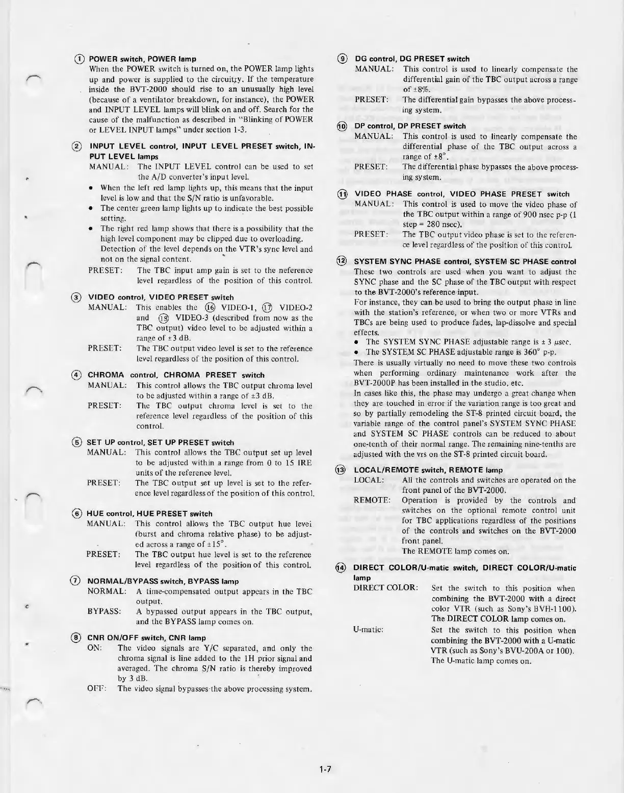
POWER switch, POWER lamp
Wh
en
th
e POWER
sw
it
ch
is turned
on,
the
POW
ER lamp lights
up and power
is
supp
li
ed
to
the cir
cu
itry.
If
the temperature
inside
the
BVT-2000 should rise to
an
unu
sually high level
(becau
se
of
a ventil
ato
r breakdown, for
in
stance), the POWER
and INPUT LEVEL l
amps
will blink
on
and off. Search for the
cause
of
th
e.
malfun
ction
as described in "Blink
in
g
of
POW
ER
or LEVEL INPUT l
amps"
under secti
on
1-3.
@ INPUT LEVEL
control,
INPUT LEVEL PRESET switch, IN-
PUT LEVEL lamps
®
MANUAL:
The
INPUT
LE
VEL co
ntrol
can be used to set
the A/D converter's input
le
vel.
• When the left red lamp
li
ghts up, this means
that
the input
level is l
ow
and that
the
S/N ratio
is
unfavorable.
• The ce
nter
green lamp
li
ghts up
to
indicate the best possible
setting.
•
Th
e right red l
amp
shows
that
th
ere is a possibility
that
the
high level
compo
nent may
be
clipped due to overloading.
Detection
of
the level
de
pends
on
the VTR's sync level and
n
ot
on the signal content.
.
PRESET: The TBC input amp gain
is
set to the neference
level regardless
of
the position
of
this
contro
l.
VIDEO control, VIDEO PRESET switch
MANUAL: Th
is
enables
the
@ VIDEO-I , @ VIDE0-2
and
@ VIDE0-3 (described from now as the
TBC ou
tput)
video level
to
be adjusted within a
PR
ESET:
range of
±3
dB.
Th
e TBC
out
put video level is set
to
the reference
level regardless
of
the position of this control.
© CHROMA control, CHROMA PRESET switch
MAN
UAL:
Thi
s
co
ntrol a
ll
ows the TBC
ou
tput
chroma level
to be adjusted with
in
a range
of
±3 dB .
PRESET:
Th
e TBC
ou
tput
chroma level is
se
t to the
reference level regardless
of
the
position
of
this
control.
@ SET
UP
control,
SET
UP PRESET switch
MANUAL: This
co
ntrol a
ll
ows the TBC
output
se
t up level
to be adjusted with
in
a range from 0 to 15 I
RE
units
of
the reference leve
l.
PRESET: The TBC
ou
t
put
set up level is
se
t to the refe
r-
ence level regardless
of
the
positi
on
of
this control.
@ HUE
cont
rol, HUE PRESET switch
MANUAL: This
contro
l allows the
TB
C
ou
tput hue levei
(bur
st and chroma relati
ve
phase) to
be
adjust-
ed
across a range
of±
15°.
PRESET: The T
BC
ou
tput
hue level is
se
t
to
the reference
level
re
gardless
of
the
position
of
thi
s
co
ntrol.
0 NORMAL/BYPASS switch, BYPASS lamp
NORMAL: A time-compensated o
utput
appears
in
the TBC
ou
tput.
BYPASS: A bypassed
ou
tpu
t appears in the TBC o
utp
ut,
and the BYPASS la
mp
comes on.
@ CNR ON/OFF switch, CNR la
mp
ON:
The
vid
eo
signals are Y/C separated, and
on
ly
the
chroma signal is line added
to
the I H prior signal and
averaged.
The
chroma S/N ratio is thereby improved
by 3 dB.
Of'f'
: The vid
eo
signal bypasses-t
he
above processing system.
1-7
®
DG
control,
DG
PRESET switch
MANUAL: This control is used to linearly compensate the
differential gain
of
the
TBC
output
across a
ra
n
ge
of
±8
%.
PRESET:
The differential gain bypasses
the
above process-
ing system.
DP
control, DP PRESET switch
MA
NUAL: This
con
trol is used
to
linearly compensate
the
differe
nti
al phase
of
the TBC ou
tput
across a
range
of
±8°.
PRESET: The differential phase bypasses
th
e above process-
in
g system.
@ VIDEO PHASE control, VIDEO PHASE PRESET switch
MANUAL: This control is used
to
move
the
video phase
of
the TBC
output
within a range
of
900
nsec p-p (1
PR
ESET:
step =
28
0 nsec).
The
TBC o
utp
ut v
id
eo phase
is
set to the referen-
ce
level regardless
of
the
pos
it
io
n
of
this
co
ntrol.
@ SYSTEM SYNC PHASE control, S_YSTEM SC PHASE control
These two controls are used when you want
to
adjust
the
SYNC phase and the
SC
phase
of
the TBC
outpu
t with respect
to the BVT-2000
's
reference inpu
t.
For
instance, they can be used to bring the ou
tput
phase in line
with the stati
on's
reference, or when two or more VTRs and
TBCs are being used to produce fades, l
ap
-dissolve and special
effects.
•
Th
e SYST
EM
SYNC PHASE ad
ju
stab
le range is ± 3 µser.
• The SYST
E.M
SC PHASE adjustable range is 360° p-p.
There is usua
ll
y virtually no need to move these two controls
when performing ordinary maintenance work after the
BVT-2000P has been installed in the studio,
etc
.
In cases like this, the phase may under
go
a great change when
they are touched in error
if
the variation range is
too
great and
so by partia
ll
y remodeling the
ST~8
printed circuit board, the
variable range
of
the
contro
l panel's SYSTEM SYNC PHASE
and SYSTEM SC PHASE controls can
be
reduced to
about
one-tenth
of
their normal range. The remaining nine-tenths are
ad
ju
sted with the vrs on the ST-8 printed circuit board.
@ LOCAL/REMOTE switch, REMOTE lamp
LOCAL: All the co
nt
rols and
sw
itches are operated
on
the
front panel
of
the BVT
-2
000,
REMOTE: Operation
is
provided by
the
controls and
sw
itches
on
the
optiona
l remote control un
it
for TBC applications regardless
of
the positions
of
the controls and switches
on
the BVT-2000
f
ront
pane
l.
Th
e R
EM
OTE lamp comes on.
@ DIRECT COLOR/U-matic switch, DIRECT COLOR/U-matic
lamp
DIRECT COLOR:
U-m
at
ic:
Set
the switch to this positi
on
when
combining
the
BVT-2000 with a direct
color VTR (such
as
Sony's
BVH-1
100).
The DIRECT COLOR lamp comes on.
Set the switch
to
this positi
on
when
combining the BVT-2000
with
a U-matic
VTR (such as Son
y's
BVU-200A
or
100).
The U-matic lamp comes on.