@
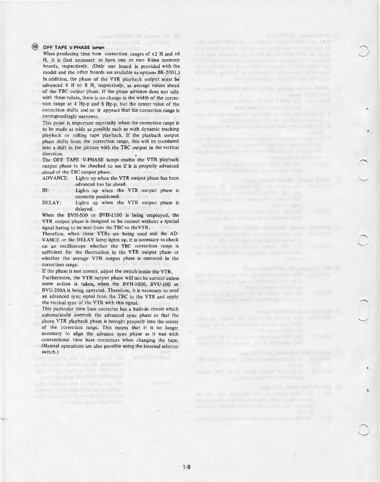
OFF
TAPE V-PHASE
lamps
When producing time base 'correction ranges
of
±2 H and
±6
H,
it
is first necessary to
ha
ve
one
or two 8-line memory
boards, respectively. (Only
one
board is prov
id
ed with the
m
ode
l and the
ot
h
er
boards are available as opti
ons
BK-2001-)
In addition, the phase
of
the VTR playback
outp
ut
must
be
advanced 4 H
or
8 H, respectively, as average values ahead
of
the
TBC
outp
ut phase.
If
the phase adv
ance
does
n
ot
tally
with these values, there is no change in
th
e
width
of
the
co
rrec-
tion
range
at
4 Hp
-p
and 8 Hp-p,
but
the center
va
lue
of
the
correc
tion
shifts and so it appears
that
the
co
rrection range is
correspondingly narrower.
This point is
im
por
tant
es
pecially when the correction range is
to
be
made as wide as possible such as with dynamic tracking
playback
or
rolling tape playback. If the playback
output
phase shifts from the correction range, this will be translated
into a shift in the picture w
ith
the TBC
output
in the verti
ca
l
direction.
The
OFF
TAP
E V-PHASE l
am
ps enable the VTR playback
output
phase to
be
checked
to
see if it is pr
ope
rly advanced
ah
ea
d
of
the TBC
ou
tpu
t phase.
ADVANCE: Lig
ht
s up when the VTR o
utp
ut phase has been
advanced
too
far ahead.
I
N:
Lights up wh
en
the
VTR
o
utput
phase is
co
rrectly
pos
itioned.
DELAY: Lig
ht
s up when
the
VTR
outpu
t phase is
delayed.
When t
he
BVH-500 or BVH-1100 is being e
mpl
oye
d, the
VTR o
utpu
t phase is designed
to
be
correct
without
a special
signal having
to
be
sent from
the
TBC
to
theVTR.
Therefore, when these VTRs are being used and
th
e AD-
VANCE
or
the DELAY lamp
li
g
ht
s up, it is necessary to c
he
ck
on an osc
ill
oscope whether the TBC correction range
is
sufficie
nt
for the fluctu
at
ion in the VTR o
utput
phase
or
wh
et
her the average
VTR
out
put
phase is centered in the
correction range.
If the phase is n
ot
correct, adjust t
he
switch inside
the
VTR.
Furthermore, the
VTR
output
phase will
not
be
co
rrect unless
some
action
is taken, when the BVH-1000, BVU-100
or
BVU-200A is being operated. Therefore, it is necessary
to
send
an
advanced sync signal from the TBC to
the
VTR and app
ly
the vertical sync
of
the VTR
with
this signa
l.
This parti
cu
lar time base
co
rrector has a built-in circuit which
a
ut
omatica
ll
y
co
ntr
ols the advanced sync phase so t
ha
t the
above VTR playba
ck
phase is brought p
rope
rly into the ce
nt
er
of
the correction
ra
nge.
Thi
s means that it is no longer
necessary
to
a
li
gn the advance sy
nc
phase as it was with
co
nventional time base
co
rr
ectors when changing the tape.
(Manual operations are also possible using the
in
te
rn
al selector
switch.)
4
1-8