EasyManua.ls Logo

Sony CDP-400 - Page 21

Sony CDP-400
48 pages
Print Icon
To Next Page IconTo Next Page
To Previous Page IconTo Previous Page
Loading...
CDP-400/501/501
ES/610ES
|
CDP-400/501/S501ES/610ES
f
1
|
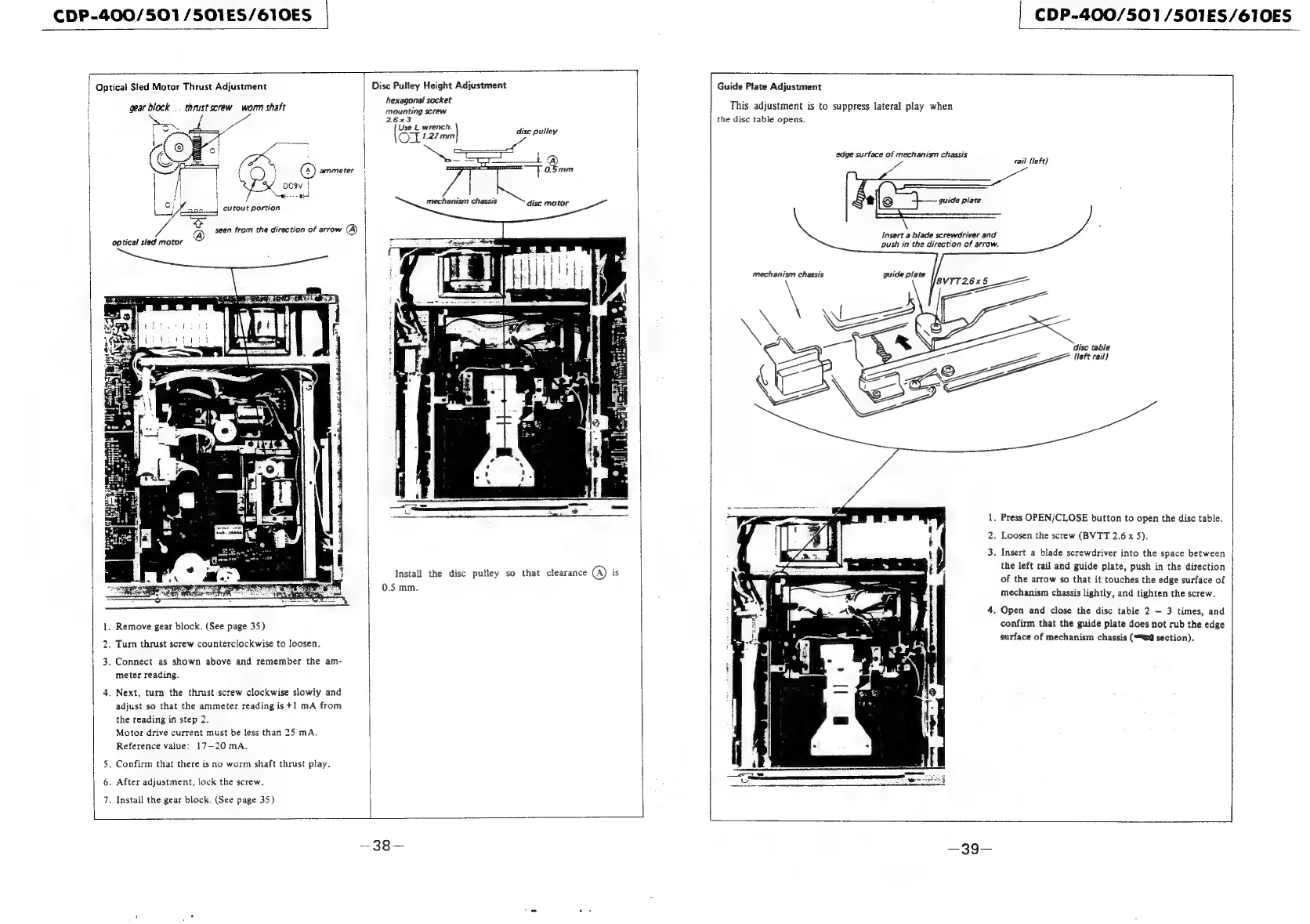
Optical
Sled
Motor
Thrust
Adjustment
Disc
Pulley
Height
Adjustment
Guide
Plate
Adjustment
hexagonal
socket
z
. .
i
gear
block
—
thrust
screw
worm
shaft
psi
crew,
This
adjustment
is
to
suppress
lateral
play
when
\
!
26x32
the
disc
table
opens.
|
(St
cli
disc
pulley
rail
{left}
7
j
edge
surface
of
mechanism
chassis
a
Bin
disc
metor
:
i
ee
guide
plate
mechanism
chassis
Insert
a
biade
screwdriver
and
push
in
the
direction
of
arrow.
mechanism
chassis
1.
Press
OPEN/CLOSE
button
to
open
the
disc
table.
2.
Loosen
the
screw
(BVTT
2.6
x
5).
3.
Insert
a
blade
screwdriver
into
the
space
between
the
left
rail
and
guide
plate,
push
in
the
direction
of
the
arrow
so
that
it
touches
the
edge
surface
of
aye MIM
eects
Tail
il
oe
i
iN
Bi
ia
i
ah
a
Install
the
disc
pulley
so
that
clearance
@)
is
0.5
mm.
7
sas
A
mechanism
chassis
lightly,
and
tighten
the
screw.
4.
Open
and
close
the
disc
table
2
—
3
times,
and
1.
Remove
gear
block.
(See
page
35)
confirm
that
the
guide
plate
does
not
rub
the
edge
2.
Turn
thrust
screw
counterclockwise
to
loosen.
surface
of
mechanism
chassis
(Wi
section).
3.
Connect
as
shown
above
and
remember
the
am-
meter
reading.
4.
Next,
turn
the
thrust
screw
clockwise
slowly
and
adjust
so
that
the
ammeter
reading
is
+1
mA
from
the
reading
in
step
2.
Motor
drive
current
must
be
less
than
25
mA.
Reference
value:
17—20
mA.
5.
Confirm
that
there
is
no
worm
shaft
thrust
play.
6.
After
adjustment,
lock
the
screw.
7.
Install
the
gear
block.
(See
page
35)