– 12 –
Table 4-3.
Button Display Button Display
1 00 10 32
2 01 >10 39
3 02 TIME 40
4 03 A – B 42
5 04 REPEAT 44
6 05 = 48
7 06 + 49
8 07 · 50
9 08 0 51
CHECK 13 ) 52
CLEAR 15 SHUFFLE 53
+ 18 p 56
– 19 P 57
CONTINUE 29
DISPLAY
86
ON/OFF
PROGRAM 31 FADER 95
Table 4-2.
Button No. Test Mode
3 Tracking servo off
8 Tracking servo on
11 S-curve measuring mode
12 All servo off
13 Top turnblack display
14 Botton turnblack display
15 Center display
16 Optimum point display
17 Optimum jitter display
18 TE traverse display
19 VC, FE and RF display
20
Autogain display
(Focus, tracking and sled)
* For button numbers 3, 8, 11, and 12, use them only when an
oscilloscope is connected.
4-3. CLV-S MODE
The spindle servo can be operated for play in the CLV-S mode by
connecting TP18 (ADJ) and after turning on the power supply.
4-4. RELEASE THE TEST MODE
Disconnect the lead wire of test point connected in first step.
4-2. ADJ MODE
Connect the TP18 (ADJ) on the BD board to the ground and turn
on the power supply. The ADJ mode is then activated and the
following operation is executed.
• There is no problem even if Guarded Frame Sync is low value
continuously during playing.
• Do not perform high speed search during an access.
• The gain of focus servo and spindle servo does not lower during
playing.
• Manual operation and measurement of the servo system are pos-
sible. (For detailed operating method, see Table 4-3. in ADJ
Mode.)
4-2-1. Button Operation Table in ADJ Mode
After all music numbers are displayed, press the TIME button,
and the jitter display mode is then set. The button functions are as
listed below.
Button Functions (Operate with remote commander.)
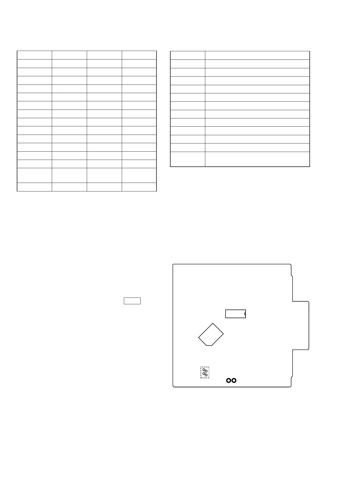
Connecting Location:
[BD BOARD] – Side B –
TP19 (AFADJ)
TP18 (ADJ)
IC102
IC351
IC361
 Loading...