– 4 –
SECTION 1
SERVICING NOTES
1-2. PREPARATION FOR ADJUSTMENT AND
MEASUREMENT
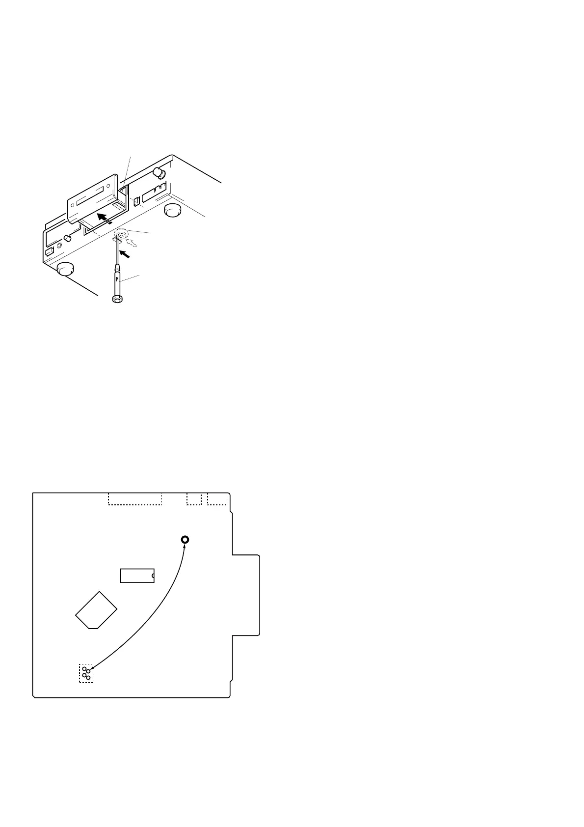
Perform connecting the IC361 pin 2 of BD board to the line of
+5V because this unit does not work without the stabilizer struc-
turally.
Connecting Location:
[BD BOARD] – Side B –
1-1. HOW TO OPEN THE DISC TRAY WHEN
POWER SWITCH TURNS OFF
1 Insert a tapering driver into the aperture of the unit bottom,
and move the limiter (LEVER) to direction of the arrow A.
2 Pull the tray to direction fo the arrow B.
*
To close the disc tray, move the driver in
the reverse direction (to IN direction).
tray
tapering driber
Limiter (LEVER)
A
B
IC361
IC351
TP (VCC)
IC102
CN102
CN103
CN105
1
2
3
4