– 14 –
Procedure:
1. Connect the oscilloscope to TP2 (FE) and TP (VC) on BD
board.
2. Connect the TP3 (FEI: IC101 pin @ª) and TP (VC) with lead
wire.
3. Turned power switch on.
4. Put disc (YEDS-18) in and turned power switch on again and
actuate the focus search. (actuate the focus search when disc
table is moving in and out.)
5. Confirm that the oscilloscope waveform (S-curve) is symmetri-
cal between A and B. And confirm peak to peak level within
3.0 ± 1.0 Vp-p.
S-curve waveform
6. After check, remove the lead wire connected in step 2.
Note: • Try to measure several times to make sure that the ratio
of A : B or B : A is more than 10 : 7.
• Take sweep time as long as possible and light up the
brightness to obtain best waveform.
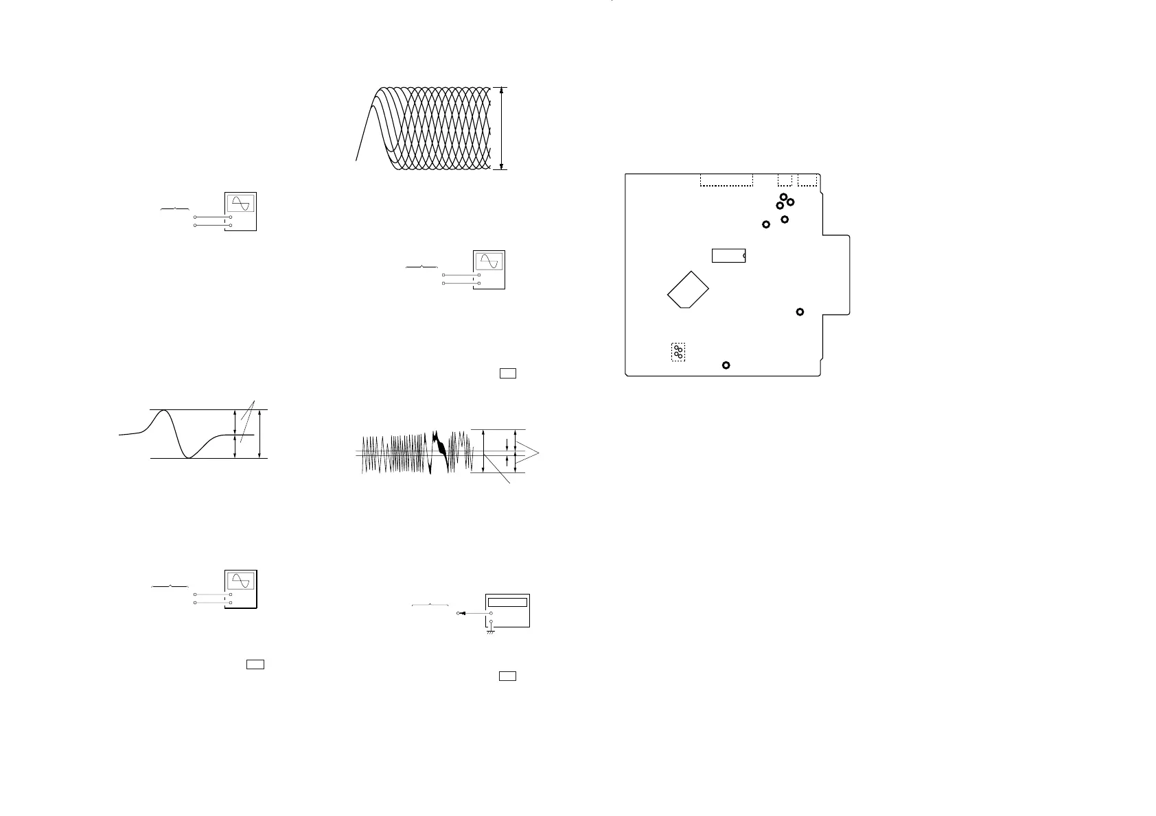
RF Level Check
Connection:
Procedure:
1. Connect the oscilloscope to TP1 (RFO) and TP (VC) on BD
board.
2. Turned power switch on. (stop mode)
3. Put disc (YEDS-18) in and press the ( button.
4. Confirm that the oscilloscope waveform is clear and check RF
signal level is correct or not.
Note: Clear RF signal waveform means that the shape “≈” can
be clearly distinguished at the center of the waveform.
RF signal waveform
SECTION 5
ELECTRICAL ADJUSTMENTS
VOLT/DIV: 200 mV
TIME/DIV: 500 ns
(with the 10: 1 probe
in use)
level: 1.2 Vp-p
+0.25
–0.20
+
–
BD board
TP2 (FE)
TP (VC)
oscilloscope
A
B
symmetry
within 3.0 ± 1.0 Vp-p
– 13 –
Notes:
1. CD block basically constructed to operate without adjustment.
Therefore, check each item in order given.
2. Use YEDS-18 disc (Part No.: 3-702-101-01) unless otherwise
indicated.
3. Use the oscilloscope with more than 10 MΩ impedance.
4. Clean an object lens by an applicator with neutral detergent
when the signal level is low than specified value with the fol-
lowing checks.
S-Curve Check
Connection:
When observing the eye pattern, set the oscilloscope for AC range
and raise vertical sensitivity.
+
–
BD board
TP4 (TE)
TP (VC)
oscilloscope
(DC range)
level: 1.3 ± 0.7 Vp-p
+
–
TP13 (XPLCK)
BD board
frequency counter
A
Symmetry
B
Procedure:
1. Connect the TP18 (ADJ) to ground and TP5 (TEI: IC101 pin
@¶) to TP (VC)with lead wire.
2. Connect the oscilloscope to TP4 (TE) and TP (VC) on BD
board.
3. Turned power switch on.
4. Put disc (YEDS-18) in and press the ( button.
5. Confirm that the oscilloscope waveform is symmetrical on the
top and bottom in relation to A Vdc, and check this level.
Traverse waveform
A/B
×
100 is ± 20 % or less.
6. After check, remove the lead wire connected in step 1.
RF PLL Free-run Frequency Check
Connection:
Procedure:
1. Connect the frequency counter to TP13 (XPLCK).
2. Turned power switch on.
3. Put disc (YEDS-18) in and press the ( button.
4. Confirm that the reading on frequency counter is 4.3218 MHz.
E-F Balance (Traverse) Check
Connection:
+
–
BD board
TP1 (RFO)
TP (VC)
oscilloscope
(AC range)
FOCUS/TRACKING GAIN ADJUSTMENT
VR in optical block is not adjusted.
As this gain has a margin, normally a little shift of gain will not
cause a problem.
If you happened to move VR and you are not sure the original
position, set it to the mechanical center.
Adjustment Location:
[BD BOARD] – Side B –
TP18 (ADJ)
IC361
CN102
CN105
TP13 (XPLCK)
TP (VC)
IC102
IC351
TP1 (RFO)
TP2 (FE)
TP5 (TEI)
TP4 (TE)
CN103
 Loading...