– 6 –
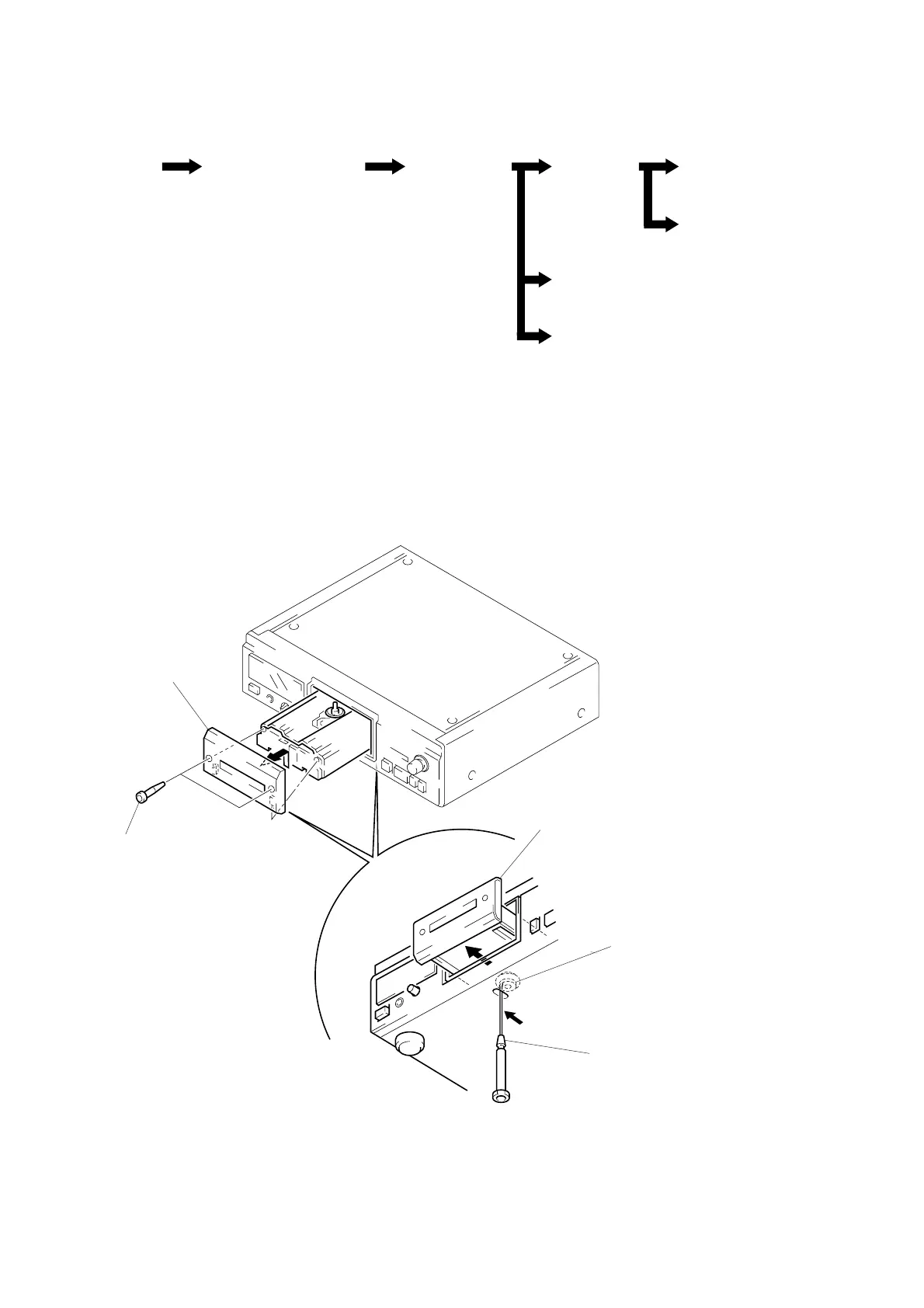
• This set can be disassembled in the order shown below.
SECTION 3
DISASSEMBLY
Note: Follow the disassembly procedure in the numerical order given.
LOADING PANEL SECTION
4
loading panel section
3
two hexagon hole bolts
(LID)
2
Pull the loading panel to
direction of the arrow
B
.
limiter (LEVER)
1
Insert a tapering driver,
and move the limiter (LEVER)
to direction of the arrow
A
.
A
B
LOADING PANEL
SECTION
(Page 6)
CASE,
FRONT PANEL SECTION
(Page 7)
MECHANISM
DECK SECTION
(Page 7)
BASE UNIT
(Page 8)
LOADING MOTOR (M103)
(Page 9)
POWER BOARD, MAIN BOARD
(Page 10)
SLED MOTOR (M101)
(Page 8)
OPTICAL PICK-UP
(KSS-213B/S-N)
(Page 9)