DCR-SR21/SR21E/SX21/SX21E_L2
2-3
#2: M1.7 X 4.0
(Black)
2-635-562-31
4.0
1.7
#12: M1.7 X 5.0 (Tapping)
(Black)
3-080-204-21
1.7
5.0
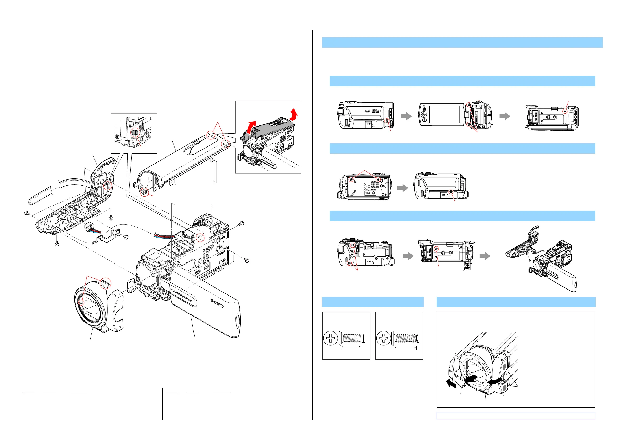
2-1. EXPLODED VIEWS
2-1-1. OVERALL SECTION-1
(SX21/SX21E)
Refer to page 2-4 about SR21/SR21E.
Ref. No. Part No. Description
Ref. No. Part No. Description
1. Remove to numerical order (1to 3) in the left figure.
DISASSEMBLY
1 #2 X 1 → #12 X 2 → #2 X 1
Screw
1 1
(Note 1)
2
1
3 2
(Note 2)
2 3
OVERALL SECTION-2
(See page 2-5)
#2
#12
#12
#2
#2
#2
1 (Claws)
2 (Claw)
2 (Claws)
3 (Claw)
2 #2 X 3
#2
Left View Back View Bottom View
#12
#2
Right View Left View
#2
#2
#2
#2
#12
Left View Bottom View
Note 2: Refer to "Assembly-1: Installation Cautions of DC-IN Harness".
3 #2 X 3 → #12 X 1
Note
Note 1:
2
1
1
2
ba
c
d
REMOVING METHOD OF F PANEL ASSY
While pushing to the a portion,
twist t he F panel assy in the
direction of the arrow b.
While pulling the belt sheet metal
(front 244) in the direction of the
arrow c, and removing the F panel
assy in the direction of the arrow d.
Belt sheet metal
(front 244)
F panel assy
1 A-1840-005-A PANEL ASSY (B), F (BLACK) (Note 1)
1 A-1840-006-A PANEL ASSY (S), F (SILVER) (Note 1)
2 A-1790-716-A CABINET (G (244)) ASSY (Note 2)
3 A-1840-020-A CABINET (246) ASSY (B), TOP (BLACK)
3 A-1840-021-A CABINET (246) ASSY (S), TOP (SILVER)
#2 2-635-562-31 SCREW (M1.7)
#12 3-080-204-21 SCREW, TAPPING, P2