Location and Function of Parts
Chapter 1 Overview
28 Chapter 1 Overview
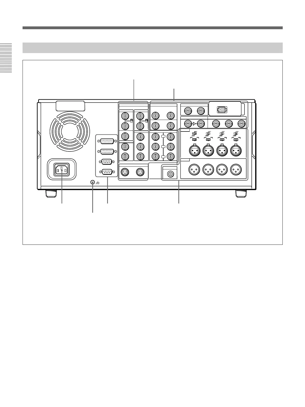
Connector Panel
REF.VIDEO
ANALOG VIDEO I/O DIGITAL AUDIO I/O(AES/EBU) SDTI(QSDI)
SDI INPUT SDI OUTPUT
i.LINK
S VIDEO
TIME CODE
MONITOR AUDIO
AUDIO IN
LEVEL
AUDIO OUT
OUT
OUT
OUT
OUT
OUT
(SUPER)
(SUPER)
IN
IN
IN
INPUT OUTPUT
IN
1
123
2
3
IN
REMOTE-OUT
REMOTE-IN
VIDEO CONTROL
~AC IN
CONTROL PANEL
CH-1
CH-2 CH-3
CH-4
CH-1
0dBm
HIGHLOW
OFF
-6dBm +4dBm
CH-2 CH-3
CH-4
OFF
ON
75Ω
VIDEO IN
VIDEO OUT
COMPONENT VIDEO
CH-1/2
CH-1/2
CH-3/4
CH-3/4
OFF
ON
75Ω
Y
R-Y
B-Y
0dBm
-6dBm +4dBm
0dBm
-6dBm +4dBm
0dBm
-6dBm +4dBm
ON
-600
Ω
LEVEL
HIGHLOW
OFF
ON
-600
Ω
LEVEL
HIGHLOW
OFF
ON
-600
Ω
LEVEL
HIGHLOW
OFF
ON
-600
Ω
1 AC IN
connector
2 Ground terminal
1 Analog video input/output section
(see page 29)
2 Digital input/output section
(see page 30)
3 External device connectors
(see page 31)
4 Analog audio input/output section
(see page 31)
This figure shows the connector panel fitted with the optional DSBK-190 i.LINK/DV Input/Output Board.
1 AC IN connector
Use the optional power cord to connect this to an AC
outlet.
2 Ground terminal
Connect this to ground.