2-10
DSR-300/P(E)/V1
2-5. NOTES ON TIGHTENING SCREWS
1. Attaching Screw to the Chassis
This unit has a small and light design, and uses numerous
M1.4 x 2.5 (1.4 mm diameter), M2 x 5, and M2 x 6 (2 mm
diameter) screws.
When tightening the above screws, be very careful of the
tightening torque. In order to prevent the chassis’s screw-
hole from damage against the excessive tightening torques,
be sure to use the following torque screwdriver and torque
screwdriver bits.
Tools Sony Part No.
Torque screwdriver J-6325-400-A
Torque screwdriver bit (For M1.4) J-6325-110-A
Torque screwdriver bit (For M2) J-6325-380-A
Screws Tightening torque
For M1.4 screws 0.09 ±0.01 N.m
(0.9 ±0.1 kgf.cm)
For M2 screws 0.19 ±0.03 N.m
(1.9 ±0.3 kgf.cm)
The above torque screwdrivers can be used for both M1.4
and M2 screws.
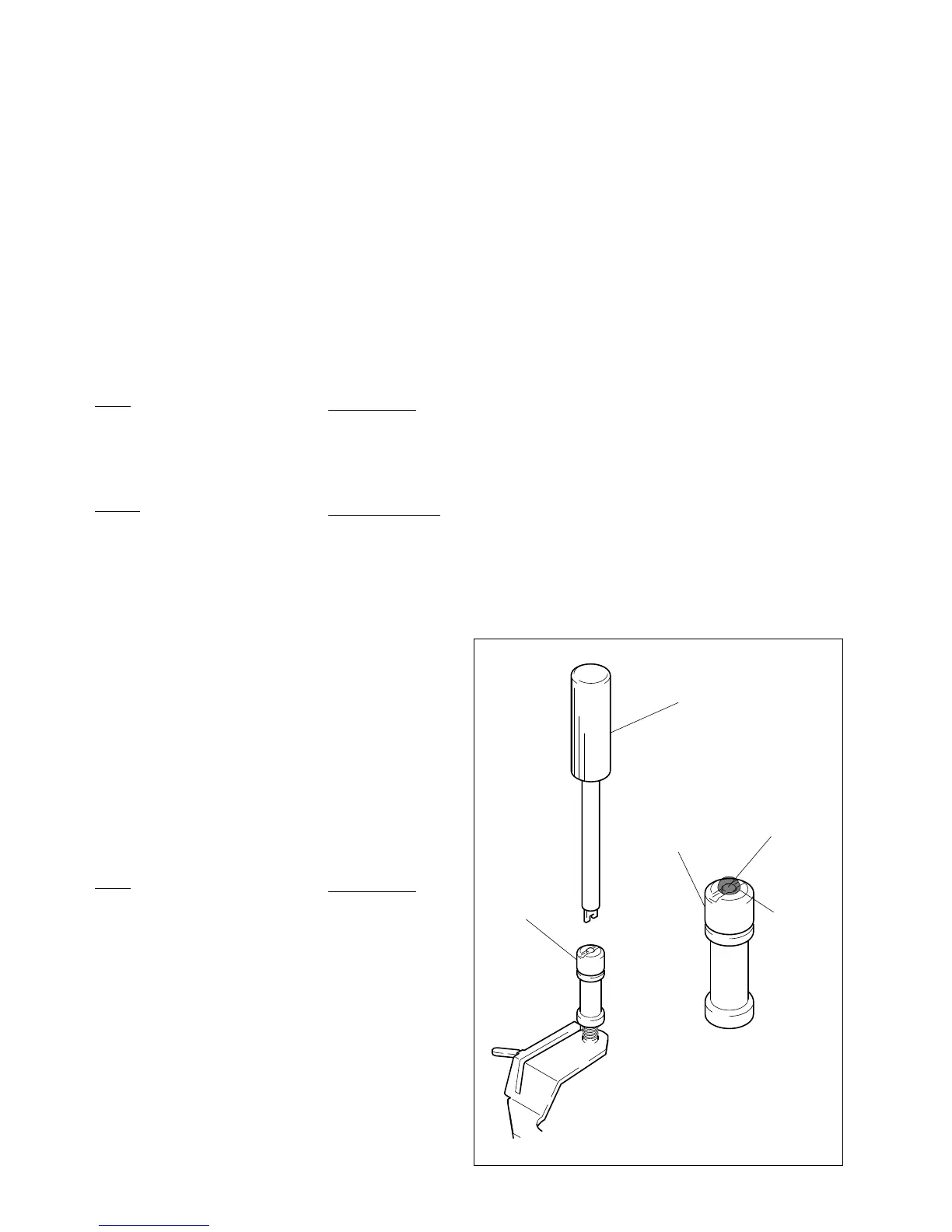
2. Screwlocking of Tape Guide’s Upper Flange
When performing the tape guide height adjustment during
tape path adjustment, use the following tape guide
adjustment screwdriver.
After adjusting the tape guide height, apply screwlocking
compound to the upper flange of tape guide and tapped
section of guide shaft screw.
Tools Sony Part No.
Tape guide adjustment screwdriver J-6082-362-A
Screwlocking compound 7-432-114-11
(Three-bond 1401B)
Point to notice when applying the screwlocking compound:
Do not apply screwlocking compound to the guides along
the tape running surface.
Tape guide adjustment
screwdriver
Guide shaft screw
Screwlock
Upper flange
Upper flange
 Loading...