7-1
NOTE:
• -XX and -X mean standardized parts, so they may
have some difference from the original one.
• Items marked “*” are not stocked since they are
seldom required for routine service. Some delay
should be anticipated when ordering these items.
• The mechanical parts with no reference number in
the exploded views are not supplied.
• Hardware (# mark) list and accessories and pack-
ing materials are given in the last of the electrical
parts list.
SECTION 7
REPAIR PARTS LIST
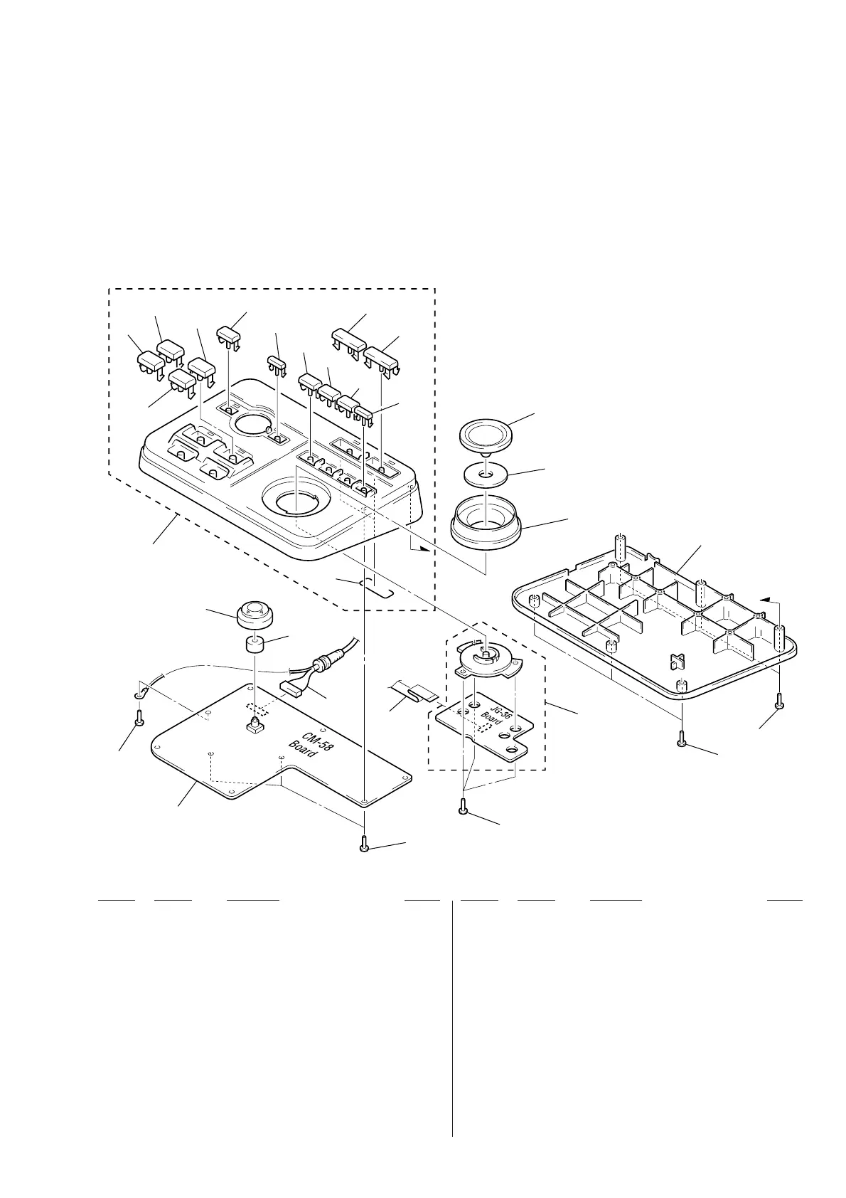
7-1. EXPLODED VIEWS
DSRM-E1/E1P
Ref. No. Part No. Description RemarkRef. No. Part No. Description Remark
(1) CONTROL UNIT SECTION
6
7
8
9
10
11
12
13
14
16
15
5
4
3
25
2
1
2
23
22
21
20
2
2
19
18
26
17
24
A
A
1 A-7073-657-A CM-58 BOARD, COMPLETE
2 7-685-134-19 SCREW +P 2.6X8 TYPE2 NON-SLIT
3 3-989-963-01 BUTTON, CONTROL
4 X-3948-689-1 CABINET (UPPER) ASSY (DSRM-E1)
4 X-3948-911-1 CABINET (UPPER) ASSY (DSRM-E1P)
5 3-968-001-51 BUTTON (TRANS) (MARK OUT)
6 3-968-001-41 BUTTON (TRANS) (MARK IN)
7 3-968-001-21 BUTTON (TRANS) (PREVIEW)
8 3-968-001-31 BUTTON (TRANS) (EDIT)
9 3-971-945-02 BUTTON (M) (FUN) (MENU)
10 3-971-948-02 BUTTON (MS) (CANCEL)
11 3-971-945-12 BUTTON (M) (FUN) (p)
12 3-971-945-22 BUTTON (M) (FUN) (()
13 3-971-945-32 BUTTON (M) (FUN) (P)
14 3-971-948-11 BUTTON (MS) (r)
15 3-971-969-01 BUTTON (L-PL) (PLAYER)
16 3-971-969-11 BUTTON (L-PL) (RECODER)
17 3-955-359-71 DIAL, JOG
18 3-989-962-01 KNOB, SHUTTLE
19 X-3948-838-1 CABINET (LOWER) ASSY
20 A-7073-658-A JG-36 BOARD, COMPLETE
21 7-685-645-79 SCREW +BVTP 3X6 TYPE2 IT-3
22 1-783-768-11 CABLE, FLAT (FCJ-1)
23 1-751-796-21 CORD, CONNECTION
24 3-971-992-01 SHAFT (BUTTON) (L)
25 3-052-467-01 CUSHION
26 3-052-026-01 SPACER (JOG)