Do you have a question about the Sony DVP-NS30 and is the answer not in the manual?
Procedure for testing AC leakage from exposed metal parts to earth ground.
Checks for unleaded solder, deterioration, line cord condition, B+ voltage, and AC leakage.
Guidance for resolving common playback, power, and picture issues.
Solutions for common player issues related to power, picture, sound, and playback.
Procedure for removing the optical device (laser pickup).
Top-level block diagram showing the player's main functional units.
Block diagram illustrating the power supply circuitry.
Block diagram for system control and signal processing.
Block diagram detailing the RF and Servo control systems.
Block diagram illustrating the audio signal processing path.
Block diagram detailing the video signal processing path.
Block diagram showing interface control signals.
Printed wiring board layout for the MV-045 board, side A and side B.
Schematic diagram of the MV-045 board, part 1 of 5.
Schematic diagram of the MV-045 board, part 2 of 5.
Schematic diagram of the MV-045 board, part 3 of 5.
Schematic diagram of the MV-045 board, part 4 of 5.
Schematic diagram of the MV-045 board, part 5 of 5.
Printed wiring board layout for the IF-124 interface board.
Schematic diagram for the IF-124 interface board.
Printed wiring board layout for the ER-037 Euro Out board.
Schematic diagram for the ER-037 Euro Out board.
Printed wiring board layout for the power block.
Schematic diagram for the power board (2P-P1-9054F).
Pin functions for the system control IC (IC101) on the MV-045 board.
Procedure for executing IOP measurement and calculating IOP in mA.
Procedure for checking emergency history and error codes.
Procedure for initializing player setup data.
Diagnosing IF-124 board functions including buttons, remote, communication, and display.
Procedure for checking and verifying output voltages of the power supply.
Procedures for adjusting video output levels and signals.
Exploded diagrams showing player parts for identification.
Exploded view of the mechanism deck assembly.
List of electrical parts for the ER-037 board.
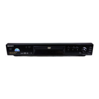
| Brand | Sony |
|---|---|
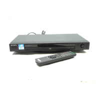
| Model | DVP-NS30 |
| Category | DVD Player |
| Language | English |