4
DVP-S9
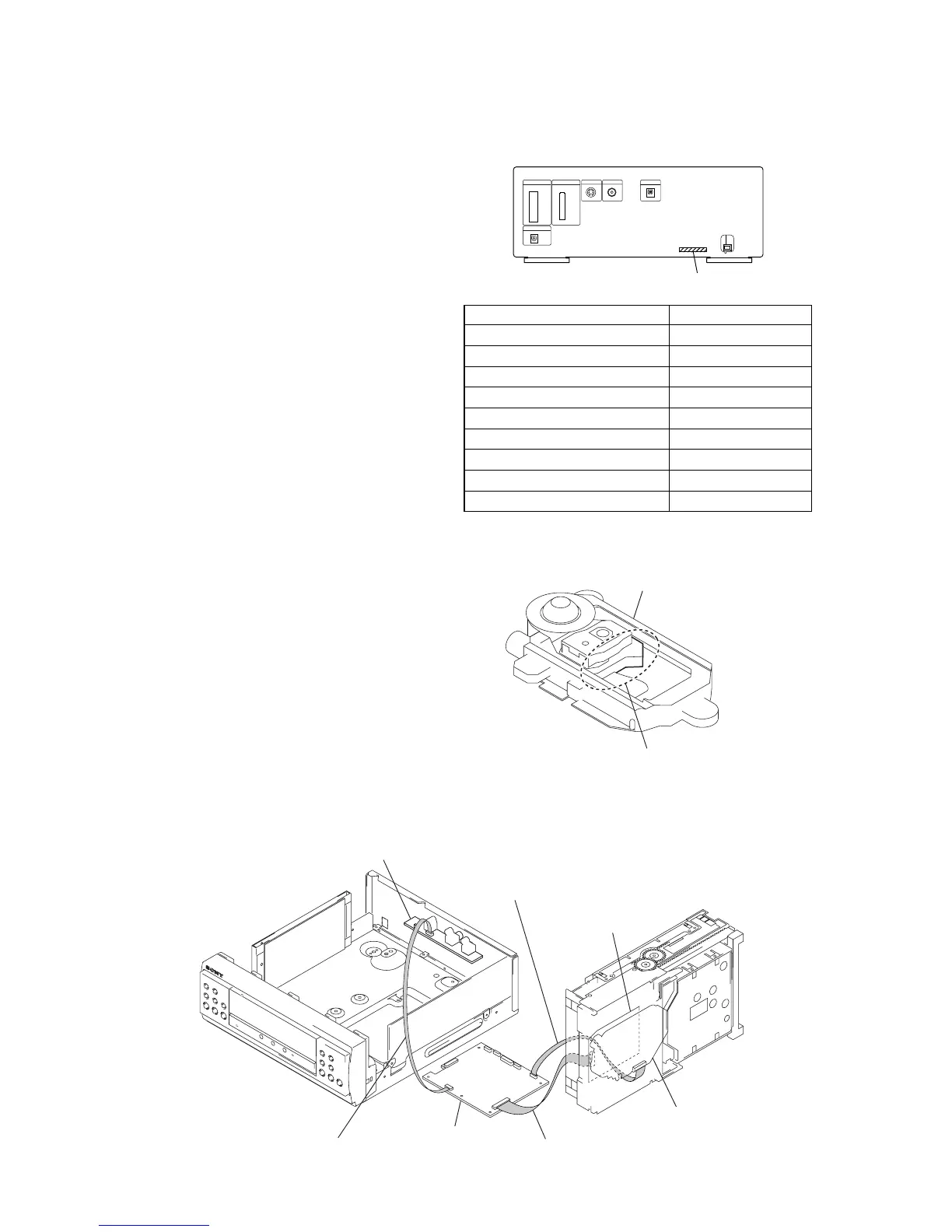
MODEL IDENTIFICATION
- Back Panel -
Model PART No.
AEP model 4-236-808-0
[]
UK model 4-236-808-1
[]
Korean model 4-236-808-3
[]
Singapore model 4-236-808-4
[]
Saudi Arabia model 4-236-808-5
[]
Austrarian model 4-236-808-6
[]
Thai model 4-236-808-7
[]
E model 4-236-808-8
[]
Mexican model 4-236-808-9
[]
TYPE A/B DISCRIMINATION
PART No.
VIDEO board
RF board
optical pick-up bloc
MB board
Connect jig (extension cable J-2501-199-A)
to the MB board (CN010) and RF board (CN002).
Connect jig (extension cable J-2501-155-A)
to the MB board (CN015) and optical pick-up block.
Connect jig (extension cable J-2501-202-A)
to the MB board (CN012) and VIDEO board (CN201).
SERVICE POSITION
In checking the CD block and another board, prepare jigs (extension cable J-2501-155-A: 300 mm 9 cores, J-2501-199-A: 300 mm 25
cores, J-2501-202-A: 300 mm 8 cores).
Ver 1.7
SILVER: KHM-240AAA (TYPE A)
BLACK: KHM-270AAA (TYPE B)
optical device
NOTE OF REPLACING THE MB BOARD
When replacing the MB board, since the adjustment value is not
set up correctly, “Drive Auto Adjustment” can’t be performed.
In this case, initialize Memory in the following procedures.
Procedure:
1. Set the test mode. (See page 12)
2. Press the [2] key of the remote commander, and set the “DRIVE
MANUAL OPERATION”. (See page 18)
3. Press the [6] key of the remote commander, and set the “2-6,
Memory Check”. (See page 20)
4. Press the [CLEAR] key of the remote commander, and initial-
ize Memory.