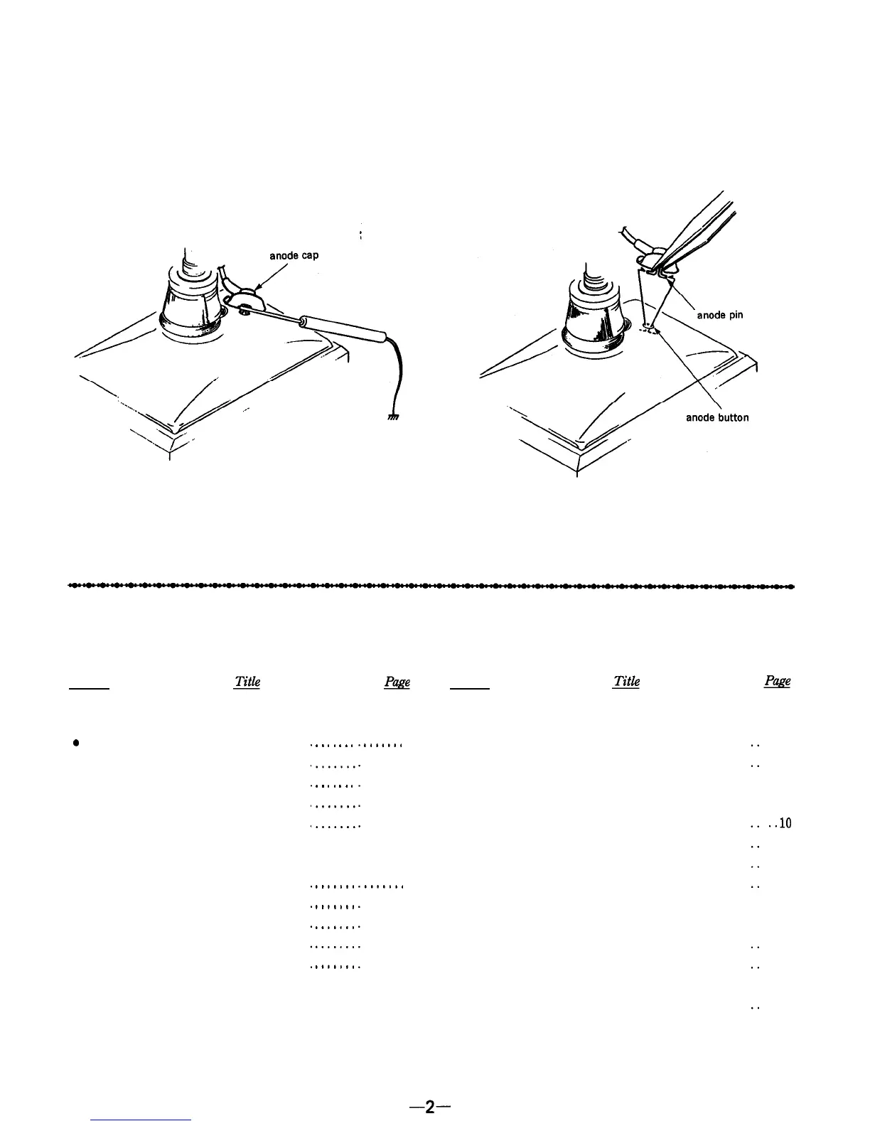
NOTEONTHEANODECAPREMOVAL
Even when the power switch is off, the voltage at the anode
cap is still high.
Remove the anode cap as follows.
1.
Discharge the anode pin to the ground.
2.
Pinch and remove the anode pin with a pair of tweezers.
At this time, be careful not to scratch the anode button.
Caution on Reinstallation :
Confirm that the anode button is inserted into the anode cap
securely.
TABLEOFCONTENTS
Section
1. GENERAL
0
Location of Controls.
.................
l
Power Sources
......................
l
Watching the TV
....................
l
Listening to the Radio
................
l
External Antenna Connection
........
2. DISASSEMBLY
2-1.
Cabinet (rear) ....................
.......
2-2.
A Board ........................
.......
2-3. Cathode-ray Tube
................
.......
2-4.
R Board ........................
.......
2-5.
Pointer Setting
..................
.......
.
.
.
.
.
.
.
.
.
.
.
.
.
.
.......
4
.......
4
.......
4
.......
5
.......
5
.......
6
.......
6
.......
6
.......
6
.......
6
Section
3. ELECTRICAL ADJUSTMENTS
3-1. Tuner Section . . . . . . . . . . . . . . . . . . . . . . . . . . . . . .
3-2. TV Section . . . . . . . . . . . . . . . . . . . . . . . . . . . . . . . .
4. DIAGRAMS
4.1.
Semiconductor Lead Layouts
............... . ..lO
4-2.
Block Diagram .............................
. . .
11
4-3.
Printed Wiring Boards
.....................
. . .
13
4.4.
Schematic Diagram
.........................
. . .
15
5. EXPLODED VIEWS
5-1. Rear Cabinet Section . . . . . . . . . . . . . . . . . . . . . . .
5-2.
Front Cabinet Section
. . . . . . . . . . . . . . . . . . . . .
6.
ELECTRICAL PARTS LIST
. . . . . . . . . . . . . . . . .
. ..21
. . . .
7
. . . .
8
. ..19
. . . 20
-2-