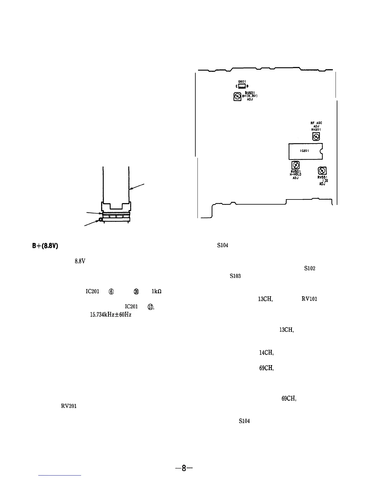
Adjustment Location : A board (component side)
3-2. TV SECTION
Setting :
MODE switch
: TV
TV BAND switch : VHF or UHF
Centering Adjustment
Procedures :
,
1.
Tune in off-the-air signal.
2.
Adjust the centering magnet so that the picture is in the
center.
3. After the adjustment, look the magnets with suitable
locking compound.
Adjustment Location :
centering magnet
adjustment screw
CRT
B+(8.8V)
Adjustment
Procedure :
Adjust RV601 for
8.8V
reading on collector voltage of Q601.
Horizontal Frequency (H-HOLD) Adjustment
Procedures :
1.
Connect between
IC201
pin
@
and pin
@
with
lkfi
resis-
tor.
2.
Connect the frequency counter to
IC201
pin
0.
3.
Adjust RV501 for a
15.734kHz+60Hz
reading on frequen-
cy counter.
4.
After the adjustment, remove the resistor in item 1.
Vertical Amplitude (V-SIZE) Adjustment
Procedures :
1.
Tune in an off-the-air signal.
2.
Adjust RV551 for the best vertical amplitude.
RF AGC Adjustment
Procedures :
1.
Tune in an off-the-air signal.
2.
Adjust
RV201
so that snow noise disappears from the
picture.
WI01
6+%!v’
ID
El
WI01
%b”J’”
RV551
V-S
I
ZE
ADJ
Tuning Adjustment
Procedures :
1.
Short
S104
(CH CALL).
(State where the display bar is shown on the screen.)
2.
Set S151 (TV BAND) to the VHF side.
3.
Receive the broadcast of 2CH by pushing
S102
(CHAN-
NEL-) or
S103
(CHANNEL+).
4.
Adjust RV103 so that the display bar is corresponded to
the position of 2CH.
5.
Receive the broadcast of 13CH, and adjust
RVlOl
so that
the display bar is corresponded to the 13CH.
Note :
Since the items 4 and 5 will interfere each other, the
adjustment is necessary for 2 to 3 times.
6.
Receive the broadcasts of 2 to
13CH,
and check if the
display bar is corresponded to each channel.
7.
Set S151 (TV BAND) to the UHF side.
8. Receive the broadcast of 14CH, and adjust RV104 so that
the display bar is corresponded to the position of 14CH.
9.
Receive the broadcast of 69CH, and adjust RV102 so that
the display bar is corresponded to the position of 69CH.
Note : Since the items of 8 and 9 will interfere each other,
the adjustment is necessary for 2 to 3 times.
10. Receive the broadcasts of 14CH to 69CH, and check if the
display bar is corresponded to the position of each chan-
nel.
11. Disconnect the
S104
shorted in the above item 1.
-8-