5-20
3-4. SERVO AND RF SYSTEM ADJUSTMENT
Before perform the servo and RF system adjustments, check that
the specified value of “27MHz Origin Oscillation Adjustment” of
“VIDEO SYSTEM ADJUSTMENT” is satisfied.
Adjusting Procedure:
1. REEL FG adjustment
2. PLL fo & LPF fo pre-adjustment
3. Switching position adjustment
4. AGC center level
5. APC & AEQ adjustment
6. PLL fo & LPF fo final adjustment
7. Hi8/Standrd8 switching position adjustment
8. Cap FG duty adjustment
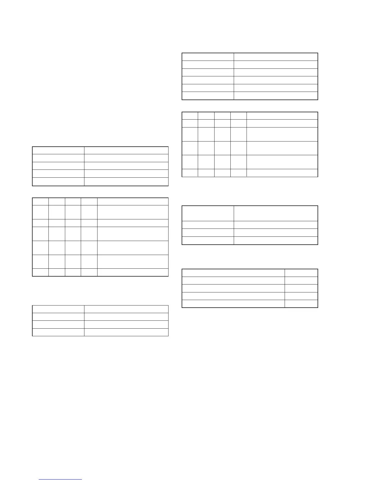
1. REEL FG Adjustment (VC-250 Board)
Compensates the dispersion of the hall elements.
Measurement Point Display data of page: 3, address: 03
Measuring Instrument Adjustment remote commander
Adjustment Page C
Adjustment Address 17, 30
Specified Value 00 or 01 or 04 or 05
Adjusting method:
Order Page
Address
Data Procedure
1 Close the cassette compartment
without inserting a cassette.
2 0 01 01 Set the data.
3 3 01 1C Set the data, and press PAUSE
button.
4 3 02 Check that the data changes to
“00”,
5 3 03 Check that the data is “00” or
“01” or “04” or “05”. (Note)
6 0 01 00 Set the data.
Note: If the data is other value, adjustment has errors. (Take an appropriate
remedial measures according to the errors referring to the following
table.)
Data Contents of defect
02, 03, 06, 07 T reel is defective
08, 09, 0C, 0D S reel is defective
0A, 0B, 0E, 0F S reel and T reel are defective
2. PLL fo & LPF fo Pre-Adjustment (VC-250 Board)
Mode VTR stop
Measurement Point Display data of page: 3, address: 03
Measuring Instrument Adjustment remote commander
Adjustment Page C
Adjustment Address 1F, 20, 22, 29
Specified Value Bit2, bit3 and bit6 are “0”
Adjusting method:
Order Page
Address
Data Procedure
1 0 01 01 Set the data.
2 3 01 30 Set the data, and press PAUSE
button.
3 3 02 Check that the data changes to
“00”.
4 3 03 Check that bit2, bit3 and bit6 are
“0”. (Note)
5 0 01 00 Set the data.
Note:
If bit2, bit3 or bit6 is “1”, there are errors.
For the error contents, see the following table. (For the bit values, refer
to “5-4. SERVICE MODE”, “4-3. 3. Bit value discrimination”. )
Bit value of page: 3, Error contents
address: 03 data
bit 2 = 1 PLL fo final adjustment is defective
bit 3 = 1 PLL fo final adjustment is defective
bit 6 = 1 LPF fo is defective
If bit 2 or bit 3 is “1”, select page: C, address: 21, set the following
data, and press the PAUSE button, and repeat steps 2 to 4.
Setting data
When the data of page: C, address: 21 is “CA”. CE
When the data of page: C, address: 21 is “CE”. C6
When the data of page: C, address: 21 is “C6”. D2
When the data of page: C, address: 21 is “D2” C2



 To Next Page