5-3
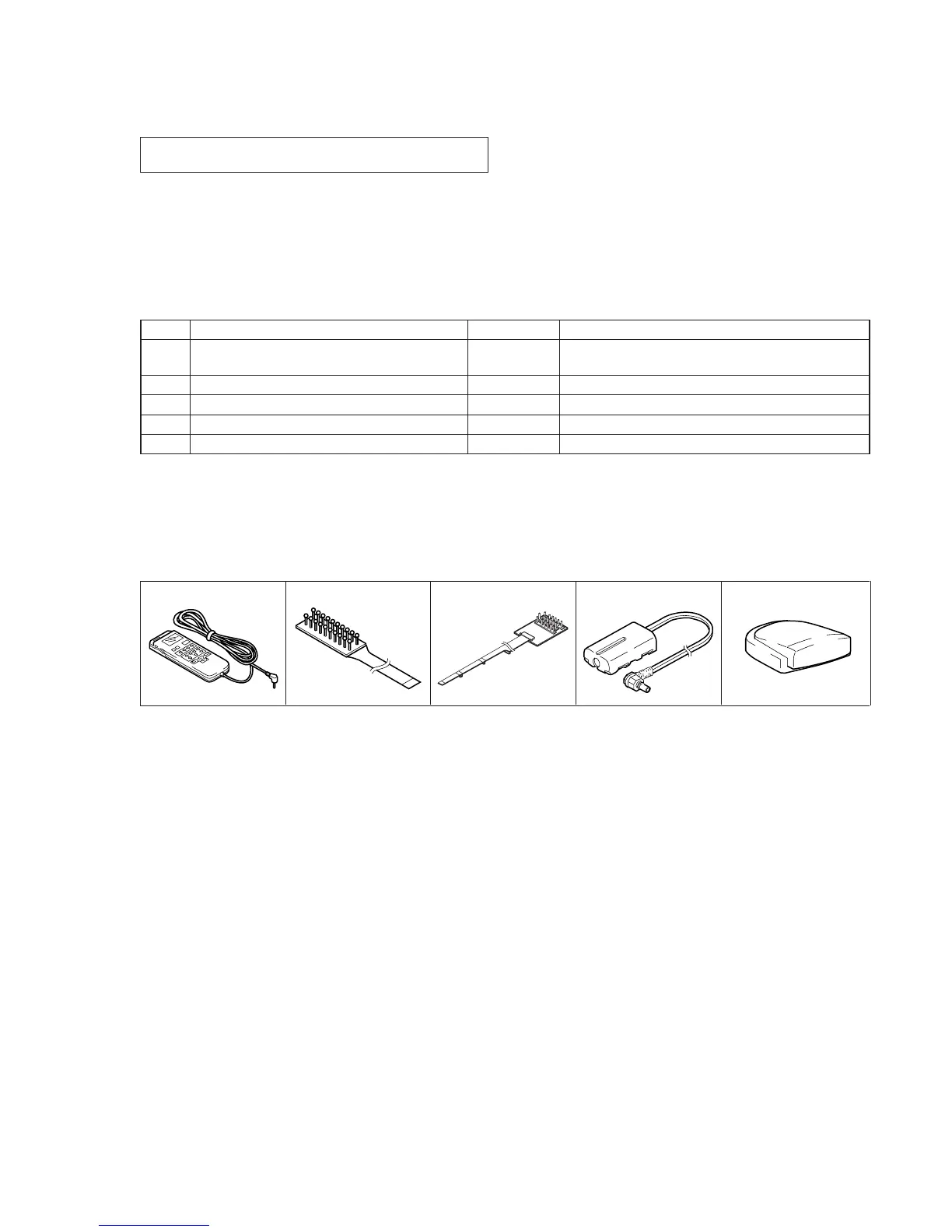
J-1 J-2 J-3 J-4 J-5
Fig. 5-1-1.
Ref. No.
J-1
J-2
J-3
J-4
J-5
Name
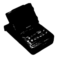
Adjustment remote commander (RM-95 upgraded).
(Note 1)
CPC-13 jig
Multi CPC jig
Power cord (Note 2)
IR receiver jig
Parts Code
J-6082-053-B
J-6082-443-A
J-6082-311-A
J-6082-223-A
J-6082-383-A
Usage
For adjusting the video section
For adjusting the LCD block
For connecting the battery terminal and DC power supply
For adjusting the IR transmitter
5-1. ADJUSTMENT PREPARATIONS
For details of the adjustment remote commander, refer to “5-4.
SERVICE MODE”.
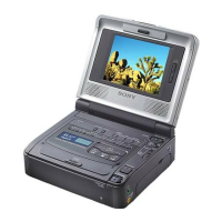
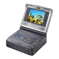
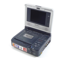
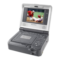
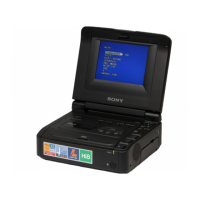
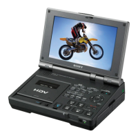
With 4-inch LCD panel: GV-D800/D800E
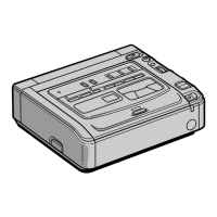
Without 4-inch LCD panel: GV-D200/D200E
1-1. PREPARATIONS BEFORE ADJUSTMENT
1-1-1. List of Service Tools
• Oscilloscope • Regulated power supply • Frequency counter • Monitor TV
• Digital voltmeter • Pattern generator
Note 1: If the micro processor IC in the adjustment remote commander is
not the new micro processor (UPD7503G-C56-12), the pages
cannot be switched. In this case, replace with the new micro
processor (8-759-148-35).
Note 2: Connect the adjustment remote commander to the LANC jack,
and set to HOLD switch to the “ADJ” side.



 To Next Page