2-1
SECTION 2
DISASSEMBLY
GV-D200/D200E/D800/D800E
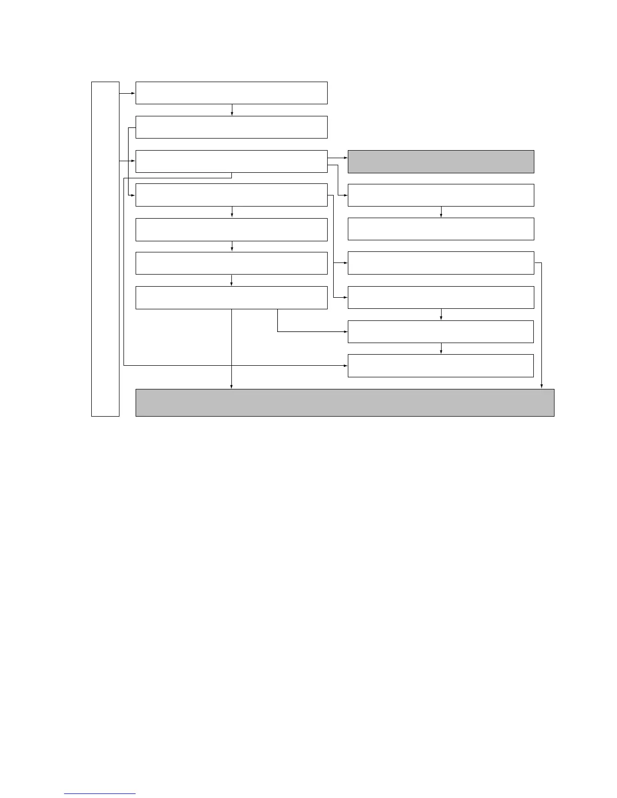
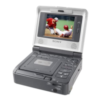
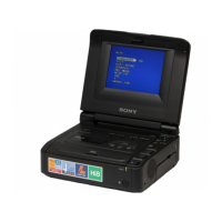
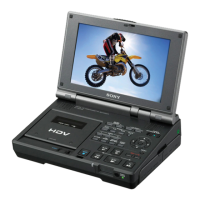
The following flow chart shows the disassembly procedure.
GV-D200/D200E/D800/D800E
2-2. Bottom cabinet assembly, FP-571 flexible board
(Lithium battery)
2-1. Cassette Lid assembly
2-3. LCD cabinet assembly (D800, D800E model)
2-5. LCD window cabinet assembly (SP-901,902)
(D800, D800E model)
2-10. Cabinet (R) block assembly, Jack frame
(IO-68, IR-38 boards)
2-12. Upper cabinet assembly,
LCD block assembly (D800, D800E model)
2-13. Hinge unit , FP-569 flexible board
(D800, D800E model)
2-6. Battery panel assembly, Battery terminal board,
DC-IN connector
2-8. Control switch block (FK-78), Loading lid
PD-130 board service position
(D800, D800E model)
2-4. PD-130, LS-56 boards (D800, D800E model)
2-9. Mechanism deck, Main frame assembly
2-11. EX-36 board, FP-570 flexible board
2-7. VC-250, FU-145 boards
[CONNECTION DIAGRAM FOR SERVICE POSITION (Mainly for voltage measurement and check)]
(VC-250, FU-145, IO-68 boards, Mechanism deck)



 To Next Page