7
HCD-C700/C900
SECTION 2
DISASSEMBLY
Note: Follow the disassembly procedure in the numerical order given.
• The equipment can be removed using the following procedure.
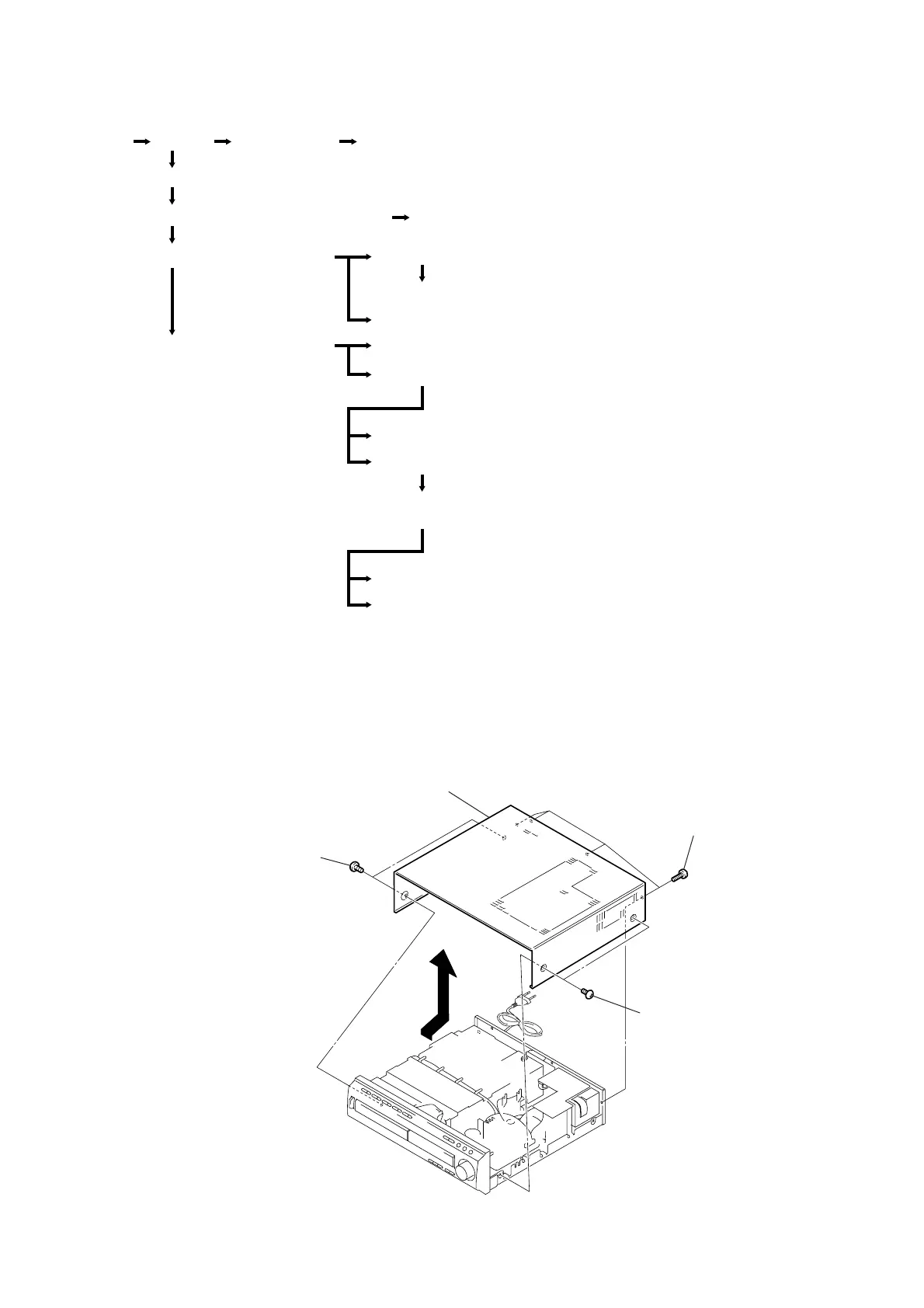
2-1. CASE (TOP)
Case(top)
POWER board
DVD mechanism deck (CDM53K-DVBU7)
Fitting base (magnet) assembly
Fitting base (guide) assembly,
Bracket (chassis)
DVD base unit (DVBU7)
Tray (240)
LOAD MOTOR board, Motor (loading) assembly
Stocker section
Gear (Gear A), Gear (Gear B), Gear (U/D slider)
Gear (chucking)
Slider (selection), Tension spring (shutter),
slider (shutter)
Chassis (mold B) section
Optical pick-up (KHM-240AAA)
CLAMP MOTOR board, Motor (clamp) assembl
RF-240 board
Tuner unit section Front panel sectionSet
4
Case
3
Four screws,
+BVTP
(3
×
8)
1
Two case screws
2
Two case screws