Do you have a question about the Sony HCD-DX155 and is the answer not in the manual?
Details audio power output and total harmonic distortion for US models DX155 and DX255.
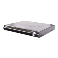
Identifies connectors and features on the rear panel of the unit.
Procedure for testing AC leakage from exposed metal parts to earth ground.
Characteristics and handling of unleaded solder.
Precautions for handling the optical pick-up block and its flexible board.
Explanation of service numbers and their corrective actions.
Capacitors on the POWER board that need discharging.
Important precautions for installing a new OP unit and handling static electricity.
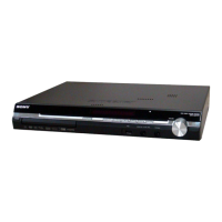
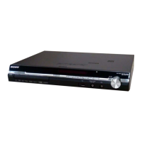
Identification of controls and indicators on the front panel.
Identification of connectors and inputs/outputs on the rear panel.
Explanation of the symbols and indicators shown on the front panel display.
Description of the functions for each button on the remote control.
Flowchart illustrating the sequence of disassembly steps for the unit.
Procedure to open the disc table mechanism when the power is off.
Procedure for attaching heat radiation sheets and heat sinks on the MAIN board.
Procedure for installing the power board for specific models.
Precautions for installing gears for sub tray 1 and 2.
Slide cam (BU) in the specified direction before re-assembly.
Rotate the gear (SS3) in the direction indicated by the arrow.
Precautions for installing cams (stocker).
Precautions for installing the gear (stocker 3).
Precautions for installing the rotary encoder (MD).
Precautions for installing the gear (BU1).
Clears all data, including preset data, to initial conditions.
Prepares the set for shipping after repair.
Procedure to enter test mode using specific button combinations.
Menu for checking and adjusting CD and DVD mirror times.
Confirms DVD mirror time value and proceeds or returns.
Confirms saved values and returns to step 7 if inconsistent.
Confirms CD mirror time value and proceeds or returns.
Confirms saved values and returns to step 15 if inconsistent.
Checks remainder against 93 for BU defect diagnosis.
Checks the RF signal level.
Diagram showing the location of various circuit boards within the unit.
Diagram illustrating signal paths for CD, DVD, and SACD playback.
Diagram illustrating signal paths for audio and tuner inputs.
Diagram illustrating signal paths for audio processing and output.
Diagram illustrating signal paths for video and component video outputs.
Table listing semiconductor reference numbers and their locations on the MAIN board.
Table listing semiconductor reference numbers and their locations.
Printed wiring board layout for the FL display.
Printed wiring board layout for the jack board.
Printed wiring board layout for the LED board.
Printed wiring board layout for the SW board.
Schematic diagram for the LED board.
Schematic diagram for the jack board.
Schematic diagram for the FL board.
Schematic diagram for the SW board.
Printed wiring board layout for the speaker board.
Schematic diagram for the speaker board.
Printed wiring board layout for the motor board.
Printed wiring board layout for the sensor board.
Printed wiring board layout for the relay board.
Printed wiring board layout for the SW (1) board.
Printed wiring board layout for the SW (2) board.
Printed wiring board layout for the encoder board.
Table listing semiconductor reference numbers and their locations.
Schematic diagram for the relay board.
Schematic diagram for the motor board.
Schematic diagram for the SW (1) board.
Schematic diagram for the SW (2) board.
Schematic diagram for the sensor board.
Printed wiring board layout for the power board.
Table listing semiconductor reference numbers and their locations.
Waveform details for IC1101 on the MAIN board.
Waveform details for IC201 on the I/O board.
Block diagram for IC2200 on the MAIN board.
Block diagrams for IC3010, IC3020, IC3030 on the MAIN board.
Block diagram for IC3050 on the MAIN board.
Block diagram for IC201 on the I/O board.
Block diagram for IC352 on the I/O board.
Block diagram for IC803 on the LED board.
Block diagram for IC802 on the FL board.
Block diagrams for IC701 and IC711 on the RELAY board.
Pin function description for IC501 on the MAIN board.
Detailed pin information for IC501.
Detailed pin information for IC501.
Pinout and description for IC1101 on the MAIN board.
Pinout and description for IC1101 on the MAIN board.
Pinout and description for IC1101 on the MAIN board.
Pinout and description for IC1101 on the MAIN board.
Pinout and description for IC1101 on the MAIN board.
Highlights safety-critical components and replacement instructions.
Exploded view of the overall unit assembly.
Instruction for folding flat type wire before replacement.
Instruction regarding EEP ROM replacement when changing the MAIN board.
List of capacitors with part numbers and specifications.
List of resistors with part numbers and specifications.
List of diodes with part numbers and specifications.
List of transformers with part numbers and specifications.
List of capacitors with part numbers and specifications.
List of transistors with part numbers and specifications.
List of resistors with part numbers and specifications.
List of diodes with part numbers and specifications.
List of ferrite beads with part numbers and specifications.
List of integrated circuits with part numbers and specifications.
List of jacks with part numbers.
List of short circuit components.
List of transistors with part numbers and specifications.
List of resistors with part numbers and specifications.
List of transistors with part numbers and specifications.
List of resistors with part numbers and specifications.
List of switches with part numbers and functions.
List of capacitors with part numbers and specifications.
List of capacitors with part numbers and specifications.
List of capacitors with part numbers and specifications.
List of diodes with part numbers and specifications.
List of ground terminal boards with part numbers.
List of fuse holders with part numbers.
List of fusible components with part numbers.
List of integrated circuits with part numbers and specifications.
List of coils with part numbers and specifications.
List of transistors with part numbers and specifications.
List of short circuit components.
List of coils with part numbers and specifications.
List of transistors with part numbers and specifications.
List of resistors with part numbers and specifications.
List of resistors with part numbers and specifications.
List of resistors with part numbers and specifications.
List of network resistors with part numbers and specifications.
Part number for the motor board.
List of switches with part numbers and functions.
Part number for the complete power board.
List of capacitors with part numbers and specifications.
List of diodes with part numbers and specifications.
List of ground terminal boards with part numbers.
List of fuse holders with part numbers.
List of fusible components with part numbers.
List of integrated circuits with part numbers and specifications.
List of coils with part numbers and specifications.
List of line filters with part numbers.
List of integrated circuits with part numbers and specifications.
List of transistors with part numbers and specifications.
List of resistors with part numbers and specifications.
List of transformers with part numbers and specifications.
List of thermistors with part numbers.
List of varistors with part numbers.
List of capacitors with part numbers and specifications.
List of connectors with part numbers.
List of diodes with part numbers and specifications.
List of integrated circuits with part numbers and specifications.
List of transistors with part numbers and specifications.
List of resistors with part numbers and specifications.
Parts list for the sensor board.
List of integrated circuits with part numbers and specifications.
Parts list for the speaker board.
List of capacitors with part numbers and specifications.
List of connectors with part numbers.
List of ground terminal boards with part numbers.
List of terminal boards with part numbers.
Parts list for the SW board.
List of switches with part numbers and functions.
Parts list for the SW (1) board.
List of switches with part numbers and functions.
Parts list for the SW (2) board.
List of switches with part numbers and functions.
List of miscellaneous parts.
History of revisions made to the service manual.