HCD-FX200/FX205
8
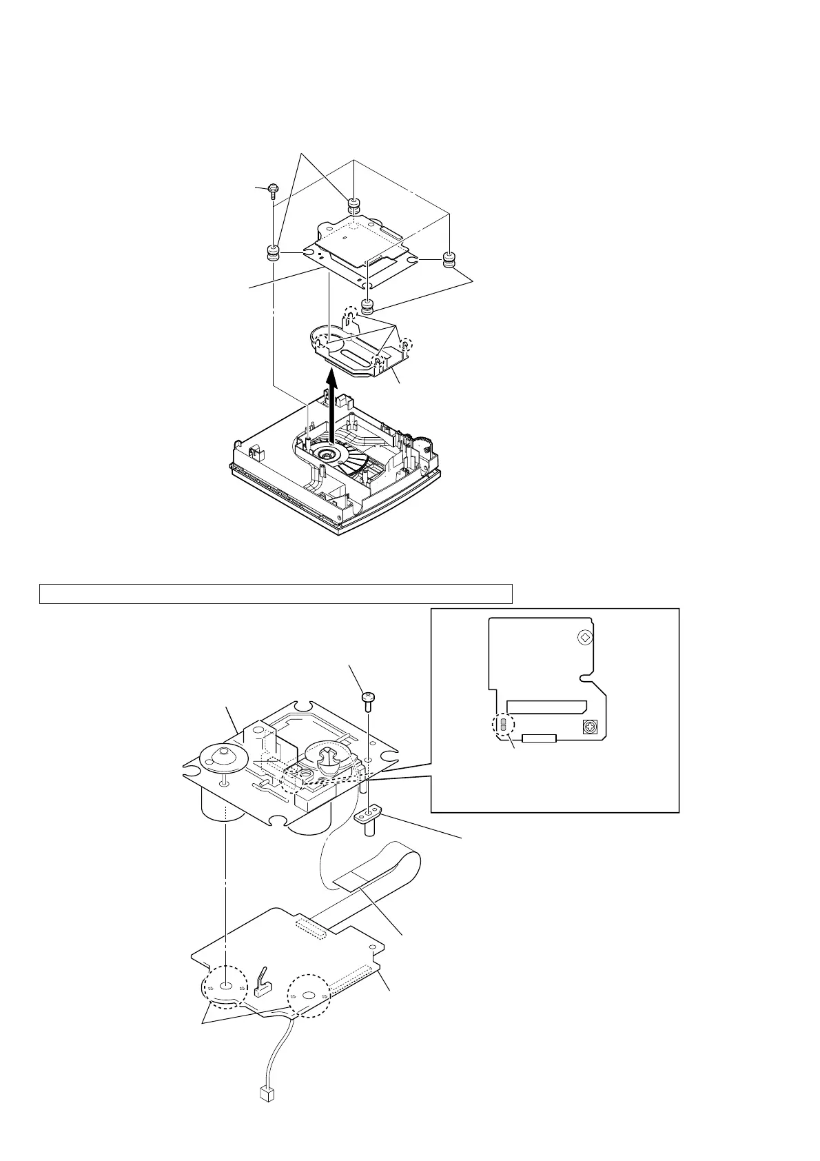
2-7. BASE UNIT (BU-D1BD73U)
Note1: This illustration sees the top panel block from base unit side.
1
four floating screws
(PTPWH M2.6)
3
two vibration proof rubbers
(red)
4
two vibration proof rubbers
(green)
6
cover (D1)
7
base unit
(BU-D1BD73U)
2
5
four claws
Note 2:
Four claws might be fixed by bond.
Please fix four claws by the bond when
you replace the cover (D1).
2-8. OPTICAL PICK-UP BLOCK (DA11MMVGP)
1
Remove four solders.
2
Solder the short-land.
4
BD73U board block
Note 2: When assembling the optical pick-up block,
remove the solder of short-land after
connecting the wire (flat type) (16 core).
7
optical pick-up block
(DA11MMVGP)
5
tapping screw (P2)
6
shaft (support)
3
wire (flat type) (16 core) (optical pick-up)
Note1: When disconnecting the wire (fl at type) (16 core) of optical pick-up block, solder the short-land.