35
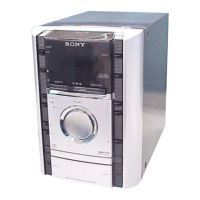
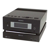
HCD-GS10/GS30DAB
• IC Pin Function Description
BD90 BOARD IC101 TC94A70FG-006 (RF AMP, DSP, MP3)
Pin No. Pin Name I/O Description
1AVSS3 — Ground terminal (Used CD analog 3.3V)
2 RFZi I RF ripple zero cross signal input terminal
3 RFRP O RF ripple signal output terminal (Used zero cross)
4SBAD/RFDC O Not used (Open)
5 FEi O Not used (Open)
6 TEi O Tracking error signal output terminal (Not used (Open))
7 TEZi I Tracking error signal input terminal (Used zero cross)
8AVDD3 — Power supply terminal (Used CD analog 3.3V)
9FOo O Focus servo equalizer output terminal
10 TRo O Tracking servo equalizer output terminal
11 VREF — REF of analog power supply terminal
12 FMO O Feed servo equalizer output terminal
13 DMO O Disc servo equalizer output terminal
14 VSSP3 — Ground terminal (Used DSP VOC 3.3V)
15 VCOi O PD output terminal (Used VCO)
16 VDDP3 — Power supply terminal (Used DSP VCO 3.3V)
17 VDD1 — Power supply terminal (Used digital 1.5V)
18 VSS1 — Ground terminal (Used digital 1.5V)
19 FGiN I FG signal input terminal (Used CAV) (Not used (Fixed to “L”))
20 Io0(/HSo) I Play speed mode flag input terminal
21 Io1(/UHSo) I Not used (Open)
22 XVSS3 — Ground terminal (Used system clock 3.3V)
23 Xi I System clock input terminal (16.934MHz)
24 Xo O System clock output terminal (16.934MHz)
25 XVDD3 — Power supply terminal (Used system clock 3.3V)
26 DVSS3 — Ground terminal (Used DAC)
27 Ro O Audio R-ch data output terminal
28 DVDD3 — Power supply terminal (Used DAC 3.3V)
29 DVR — REF voltage terminal (Used DAC)
30 Lo O Audio L-ch data output terminal
31 DVSS3 — Ground terminal (Used DAC 3.3V)
32 VDDT3 — Power supply terminal (Used Digital I/O 3.3V)
33 VSS1 — Ground terminal (Used Digital 3.3V)
34 VDD1 — Power supply terminal (Used digital 1.5V)
35 VDDM1 — Power supply terminal (Used 1M bit SRAM 1.5V)
36 SRAMSTB I 1M bit SRAM standby input terminal (Not used (Fixed to “L”))
37 RST I Reset signal input terminal
38 BUS0 I Data input terminal (BUS line)
39 BUS1 I Data input terminal (BUS line)
40 BUS2(So) I Data input terminal (Serial output)
41 BUS3(Si) I Data input terminal (Serial input)
42 BUCK(CLK) I BUS clock input terminal (Serial clock input)
43 CCE I Clip enable input terminal (U-com interface)
44 TEST I Test setting terminal (Not used (Fixed to “L”))
45 IRQ I Cut in DSP input terminal (Not used (Fixed to “L”))
46 AoUT3(Po4) O Not used (Open)
47 AoUT2(Po5) O Not used (Open)