58
HCD-RV22/RV55
• IC601 LC876964C-52S6-E (SYSTEM CONTROLLER) (PANEL BOARD (2/2))
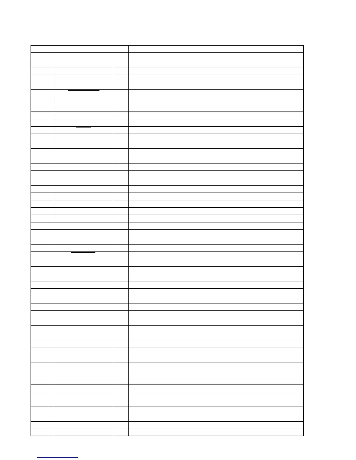
Pin No. Pin Name I/O Pin Description
1 O-MP3 CS O CS signal output to CD digital processor
2 O-MP3 LP O LP signal output to CD digital processor and motor signal output
3 I-MP3 ACK I ACK signal input from CD digital processsor and motor signal input
4 O-MP3 REQ O REQ signal output to CD digital processor and motor signal output
5 I-SCOR I CD scor signal input
6 O-MP3 RESET O RESET signal output to CD digital processor
7 I-BU1924 DATA I Data signal input
8 I-BU1924 CLK I Clock signal input
9 I-VOLUME-IN1 I Volume signal input from the encoder
10 I-VOLUME-IN2 I Volume signal input from the encoder
11 RESET I Reset signal input
12 I-XT1 I Connection for input a crystal resonator (32.768 kHz)
13 I-XT2 O Connection for input a crystal resonator (32.768 kHz)
14 VSS1 — Ground pin
15 CF1 I Connection for input a ceramic resonator (10 MHz)
16 CF2 O Connection for input a ceramic resonator (10 MHz)
17 VDD1 — Power supply pin (+1.5 V)
18 I-PROTECT I Power amplifier circuit protection signal input
19 WFR/HP/MIC-IN I Subwoofer or Headphone detection signal input
20 I-CD ENCODER I Signal input from the CD encoder
21 I-CD OPEN/CLOSE I CD tray open switch signal input
22 I-TAPE A START I TAPE A switches signal input
23 I-TAPE B START I TAPE B switches signal input
24 I-STREAM/VACS I Stream/Vacs signal input
25 I-KEY 3 I Function key input 3
26 I-KEY 2 I Function key input 2
27 I-KEY 1 I Function key input 1
28 I-SIRDS-IN I Data signal input from the remote control receiver
29 I-AC CUT I Power down signal input
30 to 42 G13 to G1 O FL tube grid signal output
43 to 45 S1 to S3 O FL tube segment signal output
46 VDD3 — Power supply pin (+3.3 V)
47 to 49 S4 to S6 O FL tube segment signal output
50 S7/METER-SW1 O FL tube segment signal output
51 –VPP — Power supply (–) pin (–26 V)
52 S8/METER-SW2 O FL tube segment signal output
53 S9/METER-SW3 O FL tube segment signal output
54 to 63 S10/SW1 to S19/SW10 O FL tube segment signal output
64, 65 S20, S21 O FL tube segment signal output
66 I-SPEC/MODEL/METER I METER switch signal input
67 I-TUNED-IN I Tuning frequency signal input
68 I-STEREO-IN I Stereo tuning signal input
69 I-AMS-IN I AMS signal input
70 I-REEL-A-IN I A deck photo sensor signal input
71 I-REEL-B-IN I B deck photo sensor signal input
72 VDD4 — Power supply pin (+3.3 V)
73 I-CD NUM SENSOR I Table address sensor switch signal input
74 O-POWER-RELAY O POWER RELAY control signal output
75 O-SYSTEM-MUTE O System muting signal output
76 O-POWER-LED O POWER LED control signal output
77 STREAM-LED6 O Illumination LED control signal output
78 STREAM-LED5 O Illumination LED control signal output


 To Next Page