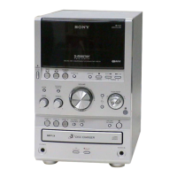
Do you have a question about the Sony HCD-SPZ70 and is the answer not in the manual?
| Brand | Sony |
|---|---|
| Model | HCD-SPZ70 |
| Category | Car Receiver |
| Channels | 4 |
| CD Player | Yes |
| MP3 Playback | Yes |
| USB Port | Yes |
| Bluetooth | No |
| Remote Control | Yes |
Details on power output, inputs, and outputs for amplifier functionality.
Specifications for the CD mechanism, laser, and frequency response.
Specifications for the tape transport mechanism and frequency response.
Specifications for FM/AM tuning, antenna, and intermediate frequencies.
Essential guidelines for safe and correct component handling and repair procedures.
Specific instructions for handling optical pickup, laser diode, and unleaded solder.
General information on system setup, basic operations, and remote control usage.
Details on sound adjustments, playing CDs, radio reception, and tape playback.
Instructions for creating custom CD programs and storing radio station presets.
Procedures for tape recording and utilizing system timers for playback or recording.
Outline of the disassembly process and initial steps for removing the case.
Detailed steps and diagrams for disassembling the front panel and tape mechanism.
Procedures for disassembling main and base unit boards.
Procedures for disassembling amplifier and tuner boards.
Procedures for clearing system data and entering general test modes for component checks.
Procedure to check the fluorescent indicator tube, LED, model, destination, and software version.
Instructions for CD ship mode, memory clear, and antitheft lock activation.
Procedure to adjust CD power settings for reducing tuner noise.
Instructions for running the CD sled motor freely for cleaning the optical pick-up.
Procedure to change AM tuning interval between 9 kHz and 10 kHz.
Precautions, torque, and tape tension measurements for mechanical adjustments.
Adjustments for the deck section, including head azimuth.
Procedure to check focus bias for the optical pick-up block.
Block diagram illustrating the CD servo control section.
Block diagram illustrating the main control and signal flow.
Block diagram illustrating the amplifier and digital power amp sections.
Block diagrams showing panel interface and power supply circuits.
Overview of the location and layout of various circuit boards within the unit.
Printed wiring board layout for the CD section.
Schematic diagram detailing the CD section circuitry.
Printed wiring board layout for the TC (Tape Control) section.
Schematic diagram detailing the TC section circuitry.
Printed wiring board layout for the main control board.
First part of the schematic diagram for the main board.
Second part of the schematic diagram for the main board.
Third part of the schematic diagram for the main board.
Printed wiring board layout for the SPZ50 amplifier board.
Schematic diagram for the SPZ50 amplifier board.
Printed wiring board layout for the SPZ70 amplifier board.
Schematic diagram for the SPZ70 amplifier board.
Printed wiring board layout for the first part of the panel section.
Printed wiring board layout for the second part of the panel section.
Schematic diagram for the first part of the panel section.
Schematic diagram for the second part of the panel section.
Printed wiring board layout for the power supply board.
Schematic diagram for the power supply board.
Example waveforms for CD, TC, Main, and FL boards to aid in troubleshooting.
Block diagrams illustrating the internal structure of CD section ICs.
Block diagrams showing the internal structure of Main Board ICs.
Block diagrams detailing the internal circuitry of amplifier section ICs.
Block diagram illustrating the internal structure of the power control IC.
Detailed pin assignments and functions for the CD DSP IC (IC201).
Overall exploded view of the unit, showing major assemblies and part locations.
Exploded view detailing the front panel components and assembly.
Exploded view of the CD mechanism and its parts.
Exploded view of the power supply section and its components.
Comprehensive list of capacitors and connectors used throughout the unit.
Comprehensive list of resistors and transistors used throughout the unit.
List of miscellaneous parts, switches, cables, and accessories.
Details of revisions made to the service manual over different versions.