EasyManua.ls Logo

Sony HCD-DJ2i User Manual

Sony HCD-DJ2i
88 pages
To Next Page IconTo Next Page
Page #1 background imageLoading...
Page #1 background image
SERVICE MANUAL
Sony Corporation
Audio&Video Business Group
Published by Sony Techno Create Corporation
HCD-DJ2i
COMPACT DISC RECEIVER
9-889-186-05
2010A04-1
©
2010.01
US Model
Canadian Model
AEP Model
UK Model
E Model
Australian Model
Ver. 1.4 2010.01
HCD-DJ2i is the tuner, USB and
iPod section in LBT-DJ2i.
Model Name Using Similar Mechanism NEW
CD Mechanism Type CDM77B-K6BD93-WOD
Optical Pick-up Name KSM-213DCP
SPECIFICATIONS
AUDIO POWER SPECIFICATION
POWER OUTPUT AND TOTAL HARMONIC DISTORTION:
USA model only
With 6-ohm loads, both channels driven, from 120 Hz – 10 kHz; rates 90
watts per channel minimum RMS power, with no more than 0.7% total
harmonic distortion from 250 miliwatts to rated output.
Ampli er section
North American model only
The following are measured at
AC 120 V, 60 Hz
Front speaker
RMS output power (reference):
150 W + 150 W (per channel at 6 Ω, 1kHz, 10% THD)
Subwoofer
RMS output power (reference):
150 W (at 6 Ω, 100 Hz, 10% THD)
Other models
The following are measured at
Mexican model: AC 127 V, 60 Hz
Saudi Arabian model: AC 120 – 127 V, 220 V or 230 – 240 V, 50/60 Hz
Other models: AC 120, 220, 230 – 240 V, 50/60 Hz
Front speaker
Power Output (rated):
90 W + 90 W (at 6 Ω, 1 kHz, 1% THD)
RMS output power (reference):
150 W + 150 W (per channel at 6 Ω, 1kHz, 10% THD)
Subwoofer
RMS output power (reference):
150 W (at 6 Ω, 100 Hz, 10% THD)
– Continued on next page –

Table of Contents

Question and Answer IconNeed help?

Do you have a question about the Sony HCD-DJ2i and is the answer not in the manual?

Sony HCD-DJ2i Specifications

General IconGeneral
Tuner BandsAM/FM
CD PlaybackYes
iPod DockYes
FunctionsCD, Cassette, Radio, iPod
Cassette DeckYes

Summary

SERVICE MANUAL

AUDIO POWER SPECIFICATION

Details power output and total harmonic distortion for different regions.

SAFETY CHECK-OUT (US MODEL)

LEAKAGE TEST

Details AC leakage testing procedures and limits.

SERVICE NOTES

Note for Repairing of the HCD-DJ2i

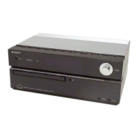
Highlights that the HCD-DJ2i requires a SA-WG2i for operation and service.

DISASSEMBLY

TEST MODE

GC TEST MODE

Explains how to enter and use the GC Test Mode for checking indicators and keys.

MC TEST MODE

Explains how to enter and use the MC Test Mode for checking amplifier and controls.

CD ERROR CODE MODE

ELECTRICAL ADJUSTMENTS

RF LEVEL CHECK

Details connecting an oscilloscope and checking RF signal waveform.

TUNER SECTION

FM TUNE LEVEL CHECK

Details connecting a signal generator and confirming tuned station reception.

DIAGRAMS

BLOCK DIAGRAM - CD Section -

BLOCK DIAGRAM - AUDIO Section -

BLOCK DIAGRAM - DIGITAL Section -

BLOCK DIAGRAM - DISPLAY/POWER Section -

SCHEMATIC DIAGRAM - CD Section (1/2) -

SCHEMATIC DIAGRAM - CD Section (2/2) -

SCHEMATIC DIAGRAM - MAIN DIGITAL Section (1/2) -

SCHEMATIC DIAGRAM - MAIN DIGITAL Section (2/2) -

SCHEMATIC DIAGRAM - MAIN AUDIO Section (1/2) -

SCHEMATIC DIAGRAM - MAIN AUDIO Section (2/2) -

SCHEMATIC DIAGRAM - REGULATOR Section

SCHEMATIC DIAGRAM - IPOD Section

SCHEMATIC DIAGRAM - USB Section

SCHEMATIC DIAGRAM - SIDE A Section

SCHEMATIC DIAGRAM - SIDE B Section -

SCHEMATIC DIAGRAM - DISPLAY Section -

SCHEMATIC DIAGRAM - MASTER VOL Section -

IC Block Diagrams

IC Pin Function Descriptions

EXPLODED VIEWS

PANEL BOTTOM SECTION

Provides an exploded view of the panel bottom section with part numbers.

CD MECHANISM SECTION

ELECTRICAL PARTS LIST

Related product manuals