Do you have a question about the Sony HCD-D670AV - Compact Disk Deck Receiver and is the answer not in the manual?
Details technical specifications for audio power, CD, tuner, and more.
Details power output, sensitivity, and impedance for the amplifier section.
Provides important notes for replacing chip components.
Warns about critical components identified by marks for safe operation.
Details the procedure for checking AC leakage from exposed metal parts.
Provides notes on handling the optical pick-up block.
Gives instructions for checking laser diode emission safely.
Step-by-step guide to disassembling the front panel and main board.
Instructions for disassembling the TC mechanism deck.
Steps for disassembling the CD mechanism deck.
Important precautions before performing mechanical adjustments.
Procedures for electrical adjustments in the deck section.
Steps to adjust the azimuth of record/playback heads.
Procedure for adjusting tape speed on Deck A.
Steps to adjust playback levels for both decks.
Procedure for adjusting record bias current on Deck B.
Steps to adjust record level on Deck B.
Procedure for adjusting AM tuned level.
Procedure for adjusting FM tuned level.
Steps to adjust focus bias.
Procedure for checking the S-curve.
Procedure for checking RF signal level.
Procedure for checking E-F balance.
Schematic diagram for the CD section.
Schematic diagram for tuner section of specific models.
Schematic diagram for tuner section of AEP/UK/G/IT models.
Schematic diagram for the CD panel section.
Schematic diagram for the deck section.
Schematic diagram for the main section.
Schematic diagram for the panel section.
Schematic diagram for the power section.
Schematic diagram for the CD motor section.
Parts list for the power amplifier section.
Parts list for the power amplifier and S. Woofer.
| CD Playback | Yes |
|---|---|
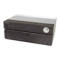
| Brand | Sony |
| Model | HCD-D670AV |
| USB Port | No |
| Bluetooth | No |