EasyManua.ls Logo

Sony HCD-V515 User Manual

Sony HCD-V515
29 pages
To Next Page IconTo Next Page
Page #1 background imageLoading...
Page #1 background image
MICROFILM
SERVICE MANUAL
MINI Hi-Fi COMPONENT SYSTEM
E Model
Chinese Model
SPECIFICATIONS
HCD-V515
Dolby noise reduction manufactured under license
from Dolby Laboratories Licensing Corporation.
“DOLBY” and the double-D symbol a are trade-
marks of Dolby Laboratories Licensing Corporation.
HCD-V515 is the Amplifier, Video CD
player, Tape Deck and Tuner section in
MHC-V515.
– Continued on next page –
HCD-V515 is almost same as HCD-V717.
This manual contains only the points which differ
from HCD-V717.
Please refer to HCD-V717 service manual (9-922-879- )
previously issued for other information.
w
w
w
.
x
i
a
o
y
u
1
6
3
.
c
o
m
Q
Q
3
7
6
3
1
5
1
5
0
9
9
2
8
9
4
2
9
8
T
E
L
1
3
9
4
2
2
9
6
5
1
3
9
9
2
8
9
4
2
9
8
0
5
1
5
1
3
6
7
3
Q
Q
TEL 13942296513 QQ 376315150 892498299
http://www.xiaoyu163.com
Question and Answer IconNeed help?

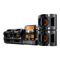
Do you have a question about the Sony HCD-V515 and is the answer not in the manual?

Sony HCD-V515 Specifications

General IconGeneral
Power Output100W
CD PlayerYes
TunerAM/FM
Cassette DeckYes
Remote ControlYes
SpeakersIncluded
TypeMini Hi-Fi Component System

Summary

Service Manual Introduction and Specifications

Amplifier Section Specifications

Technical specifications for the amplifier section, including power output and impedance.

System Specifications

Specifications for Video CD/CD player, Tuner, and Tape player sections.

Servicing Notes and Safety Precautions

Handling Precautions

Notes on handling optical pick-up, laser diode, and flexible circuit boards.

Component Replacement and Repair

Guidelines for replacing chip components and repairing circuit boards.

Safety Warnings

Critical warnings regarding safety components and their proper replacement.

Controls and Operation

Location of Controls

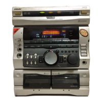
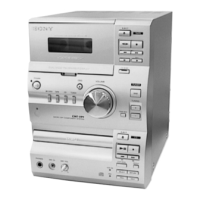
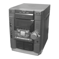
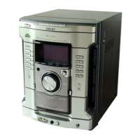
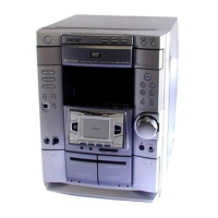
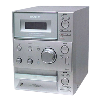
Identification and location of all front panel controls and indicators.

Setting the System Clock

Step-by-step guide to set the internal clock time of the system.

Technical Diagrams and Schematics

Notes for Diagrams and Schematics

Explanation of symbols, notations, and abbreviations used in circuit diagrams.

Main Section Schematics

Detailed circuit diagrams for the main board, presented in multiple parts.

Power Amplifier Schematics

Specific schematic diagrams detailing the power amplifier circuitry.

Transformer Section Schematics

Circuit diagrams for the transformer and power supply components.

Exploded Views

Case Section Exploded View

Visual diagram of the case assembly with part numbers.

Front Panel Section Exploded View

Visual diagram of the front panel assembly with part numbers.

Chassis Section Exploded View

Visual diagram of the chassis assembly with part numbers.

Parts List and Hardware

Electrical Components List

Comprehensive list of electrical components with part numbers and specifications.

Hardware List

List of hardware components like screws used in the assembly.

Related product manuals