HCD-V515
– 15 –
– 16 –
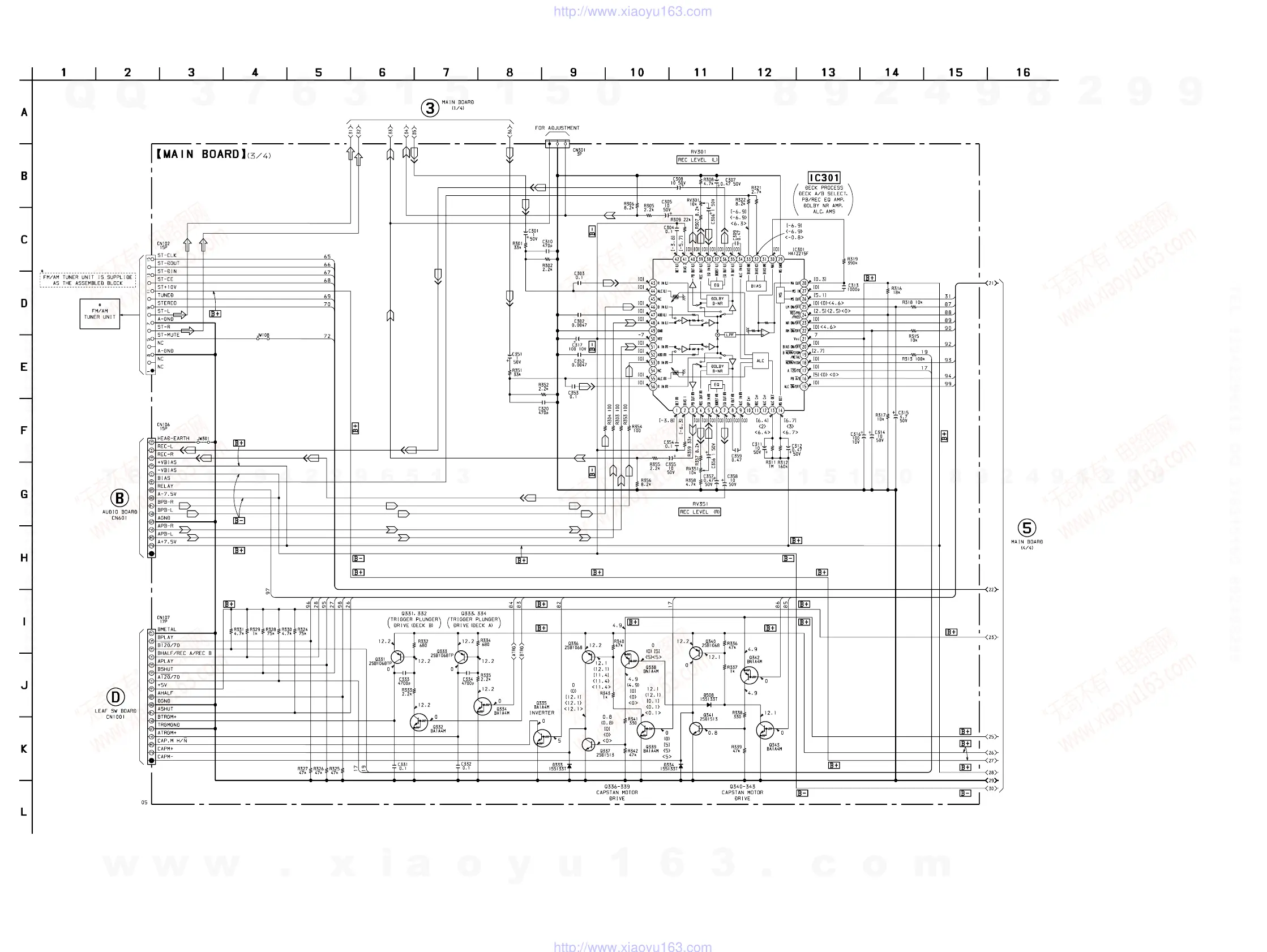
3-5. SCHEMATIC DIAGRAM – MAIN Section (3/4) –
• Voltages and waveforms are dc with respect to ground
under no-signal (detuned) conditions.
no mark : FM { } : PB (DECK A)
( ) : CD [ ] : PB (DECK B)
< > : REC
(See Page 50
on HCD-V717
Service manual)
(See Page 48
on HCD-V717
Service manual)
(Page 17)
(Page 11)
w
w
w
.
x
i
a
o
y
u
1
6
3
.
c
o
m
Q
Q
3
7
6
3
1
5
1
5
0
9
9
2
8
9
4
2
9
8
T
E
L
1
3
9
4
2
2
9
6
5
1
3
9
9
2
8
9
4
2
9
8
0
5
1
5
1
3
6
7
3
Q
Q
TEL 13942296513 QQ 376315150 892498299
TEL 13942296513 QQ 376315150 892498299
http://www.xiaoyu163.com
http://www.xiaoyu163.com
 Loading...