18
Locations and Functions of Parts
Input an HD tri-level reference sync signal or SD reference
sync signal (black burst signal) for the sequence-lock between
the camera control units, to the upper of the two connectors.
The input signal is output from the lower connector as is (loop-
through output).
When not using the OUT connector, terminate it at 75 ohms.
b PIX OUT (picture monitor output) connector (BNC-
type)
Outputs the video signal for a picture monitor selected with the
PICTURE MONITOR button of an RCP-1000 series Remote
Control Panel or MSU-1000 series Master Setup Unit.
For details on these operations, refer to the Master Setup Unit
or Remote Control Panel manuals.
c WF OUT (waveform monitor) connector (BNC-type)
Outputs the video signal for a waveform monitor selected with
the WF MONITOR button of an RCP-1000 series Remote
Control Panel or MSU-1000 series Master Setup Unit.
For details on these operations, refer to the Master Setup Unit
or Remote Control Panel manuals.
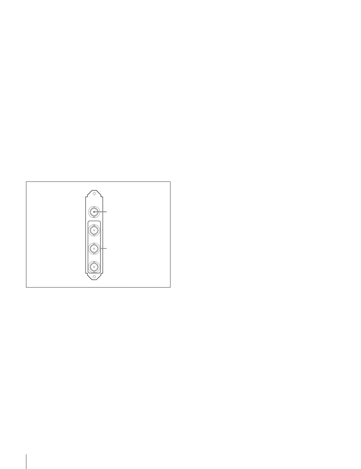
VDA-C Board
a VBS (composite video signal output) connector (BNC-
type)
The signal from the video camera may be output as an analog
composite signal.
b R/R-Y, G/Y, B/B-Y (component video signal output)
connectors (BNC-type)
The signal from the video camera may be output as a R/R-Y,
G/Y, B/B-Y component signal or an RGB component signal.
VBS
R/R-Y
G/Y
B/B-Y
VDA-C
1
2