16
Locations and Functions of Parts
Internal Switches
Note
To reduce the risk of electric shock, fire or injury, do not open
the cabinet. To adjust the internal settings, refer to qualified
service personnel.
There are no internal switches on HDCU2000.
HDCU2500 Internal Switches
The following switches are located inside the unit, behind the
front panel:
a Internal main power switch
When an abnormality has occurred, and power cannot be cut
off with the POWER switch on the front panel, you may turn off
the unit using the internal main power switch. When the switch
is set to OFF, setting the POWER switch on the front panel to
ON doesn’t turn on the unit.
HKCU2007 3G/HD SDI Output
Expansion Unit (optional)
Note
To reduce the risk of electric shock, fire or injury, do not open
the cabinet. To adjust the internal settings, refer to qualified
service personnel.
The HKCU2007 3G/HD SDI Output Expansion Unit consists of
a DRX front board and an HIF rear board.
When these boards are installed in the front and rear
expansion slots of the unit, the number of 3G/HD-SDI output
connectors increases by four. These can also be installed on
HDCU2000/2500’s expansion slots.
The format of SDI signals output via each upper/lower pair of
connectors on the HIF board can be set.
For details on installation, contact a Sony service or sales
representative.
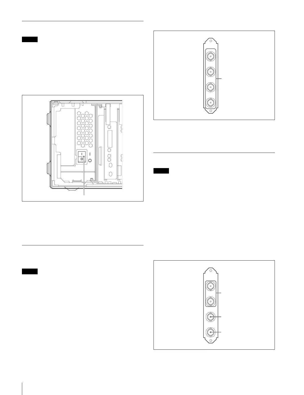
HIF-57 Board
a SDI OUT 1, 2, 3, 4 (3G/HD serial digital interface output
1-4) connectors (BNC-type)
The signal from the video camera may be output as four 3G-
SDI or HD-SDI signals.
HKCU1001 SD Encoder Unit (optional)
Note
To reduce the risk of electric shock, fire or injury, do not open
the cabinet. To adjust the internal settings, refer to qualified
service personnel.
The HKCU1001 consists of an EN-A front board and a VDA-A
rear board.
When these boards are installed in the front and rear
expansion slots of the unit, the unit outputs SD composite
signals, waveform monitor output signals, and picture monitor
output signals through the VDA-A board’s connectors.
For details on installation, contact a Sony service or sales
representative.
VDA-A Board
1
1
3
2
4
SDI OUT
1
VDA-A
1
2
PIX
OUT
WF
OUT
VBS
1
2
3