34
Setup Menu
Menu List
Note
The following conventions are used in the menu list table.
Settings column values (e.g. ON, OFF, 0): Default settings
Execute via ENTER: Press the CONTROL knob or move the CANCEL/ENTER lever to the ENTER position to execute.
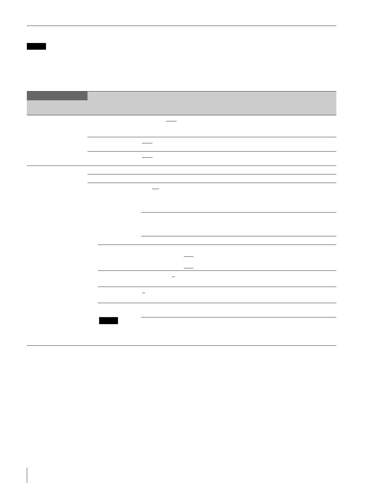
SYSTEM OPERATION menu
SYSTEM OPERATION
Page name
Page No.
Item Settings Description
<OUTPUT SELECT>
S01
OUTPUT CAMERA, BAR
, TEST1, TEST2 Selects the output signal.
TEST1 and TEST2 are not selectable if there is no
communication with the camera.
PIX ENC
, R, G, B, R&G, G&B, R&B,
RGB
Selects the PIX connector output signal.
WFM ENC
, R, G, B, SEQ, R&G, G&B,
R&B, RGB
Selects the WFM connector output signal.
<GENLOCK PHASE>
S02
CONTROL (REMOTE), (LOCAL)
REFERENCE (NONE), (EXT IN) Displays the status of the reference signal input.
GENLOCK HD, SD This unit’s GEN LOCK mode: displays the lock
status and format.
HD: HD
SD: SD
(OK), (NG) Sets the lock status of the external reference signal.
(OK): Locked
(NG): Unlocked
External reference signal format Displayed only when a reference signal is present.
H STEP When GENLOCK mode is HD:
–3.01 to 3.45 µsec 0.00
When GENLOCK mode is SD:
–8.29 to 9.48 µsec 0.00
Horizontal phase (STEP)
Displays the sub-reference signal format.
COARSE –99.9 to 99.9 0
Horizontal phase
Displays the sub-reference signal format.
V PHASE 0
to 7 Vertical phase (line)
Displays the sub-reference signal format.
SUB-REF
Note
Displayed only
when HKCU1003
is connected
(NONE), (EXT IN) Displayed only when a sub-reference signal is
present.
(UNKNOWN), (Frame Gate), (HD),
(SD)
Sub-reference signal format display