6
Overview
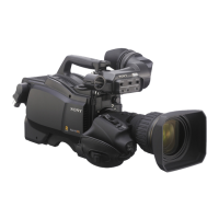
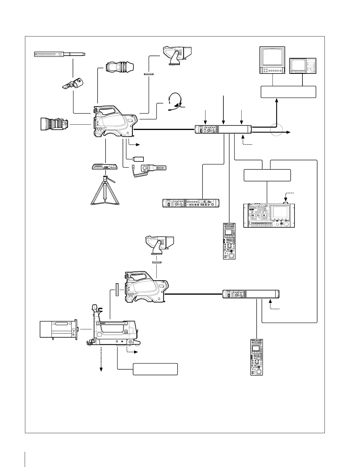
System operation example (two HSC300RF/HSC100RF cameras with camera control units
a)
)
Lens
(for ENG/EFP)
VCT-14
Tripod Adapter
Lens
(for studio use)
Large Lens Adapter
HDLA1500 series
HDVF-550/C550W/C730W
Viewfinder
HDVF-200/C35W
Viewfinder
Optical fiber cable
CAC-12
Microphone
Holder
HSC300RF
HSC100RF
CAC-6 Return
Video Selector
Intercom headset
Microphone
BKP-7911
Script Holder
HSCU300RF
Camera
Control Unit
MSU-1000/1500
Master Setup Unit
CCA-5 cable
Picture Monitor
Waveform Monitor
Video router
Camera hangers
c)
d) For 12 V DC general-purpose output, the serial number must be
the following or higher:
HDLA1500: 13001 or 43001, HDLA1503: 52001,
HDLA1505: 11001, 41001 or 401001, HDLA1507: 401001
HDVF-550/C550W/C730W
Viewfinder
Video output
HD-SDI/SD-SDI/VBS
AC power
AC power
Tripod for portable
camera
LAN cable
Hub
LAN cable
HSC300RF
VF attachment shoe
b)
12 V DC general-
purpose power supply
(Max. 5 A)
d)
Power supply for script light
Sync
signal input
Power supply for
script light
Return video input
Prompter
video input
to router/
switcher
BNC BNC
VF attachment shoe
b)
Optical fiber cable
HSCU300RF Camera
Control Unit
CCA-5 cable
LAN cable
a)
RCP-1000 series
Remote
Control Panel
AC power
a) Supported only when using the multi-camera system option in the CCU
b) Supplied with the HDVF-550/C550W/C730W, Part No.: A-7612-405-E
c) Supplied with the HDLA1500/1505, Part No.: A-1128-405-A
HKCU-FP2
Front Control Panel
RCP-1000 series
Remote
Control Panel
(mounts on
HSCU300RF
front panel)
USB drive
 Loading...