9
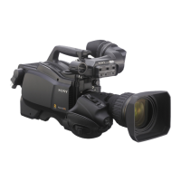
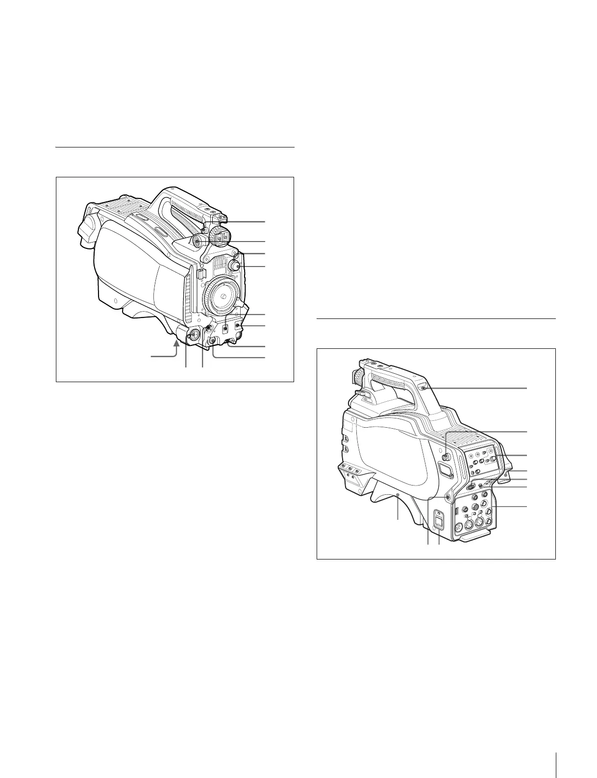
Locations and Functions of Parts
o Menu control knob (rotary encoder)
Selects settings from menu items displayed on the viewfinder
screen (by rotating it) and confirms settings (by pushing it).
This knob functions the same as the menu control knob on the
rear operation panel.
p DC power supply output connector (2-pin)
Supplies up to 2.5 A current (10.5 V to 17 V DC) to an external
device.
Front Left
a Shoulder strap fitting post
Attach one end of a shoulder strap (optional, part No. A-6772-
374-C) to this fitting post and the other end to the fitting post
on the other side of the camera.
b VF (viewfinder) connector (20-pin)
Connects to the cable of the viewfinder (optional).
c CC filter select knob (HSC300RF/HSC300R only)
Selects the built-in CC filters (A: cross, B: 3200K, C: 4300K,
D: 6300K).
d ND filter select knob
Selects the built-in ND filters (1: clear, 2: 1/4 ND, 3: 1/16 ND,
4: 1/64 ND).
e SHUTTER switch
When the camera is used in standalone status (without
connection to a CCU), use this switch to turn the electronic
shutter ON or OFF and to change (SEL) the shutter speed and
shutter mode.
For details, see “Setting the Electronic Shutter” on page 18.
f AUTO W/B BAL (white and black balance automatic
adjustment) switch
Automatically adjusts white and black balance when the
camera is used in standalone status (without connection to a
CCU).
WHT: Automatically adjusts white balance.
BLK: Automatically adjusts black balance.
For details, see “Adjusting the Black Balance and White
Balance” on page 16.
g INTERCOM LEVEL knob
Adjusts the intercom/earphone volume level.
The intercom level adjustment is enabled when the LEVEL/
MIC switch on the rear operation panel is set to “FRONT.”
h RET (return video) button
When this button is pressed, the picture on the viewfinder
changes to the return video signal selected with the RET 2/3/
4 select switch (page 10) on the rear operation panel.
You can also assign other functions to this button using the
menu in the viewfinder.
i LENS connector (12-pin)
Connects to the lens cable. The camera can control the lens
functions through this cable.
j MIC 1 IN (microphone 1 input) connector (XLR 3-pin)
Connects to a microphone.
This connector and the AUDIO IN CH1 connector are
alternately activated with the MIC 1 select switch on the rear
connector panel.
k Tripod mount (bottom)
Attaches to a VCT-14 Tripod Adapter when mounting the
camera on a tripod.
For details, see “Mounting the Camera to a Tripod” on page 15.
Rear
a Tally lamp and switch
ON: The tally lamp lights when a tally signal is input to the
connected CCU or a call signal is generated in response to
pressing of a CALL button.
OFF: The tally lamp is disabled.
b Shoulder strap fitting post
c Operation panel (see “Operation Panel”)
d Camera control unit (CCU) connector (optical fiber/
triax connector)
Connects to a HSCU300RF/HSCU300R camera control unit
using an optical fiber cable or a triax cable.
qa
1
2
4
3
5
6
7
8
7
6
4
1
2
3
5
0
 Loading...