2-4
HXR-NX3
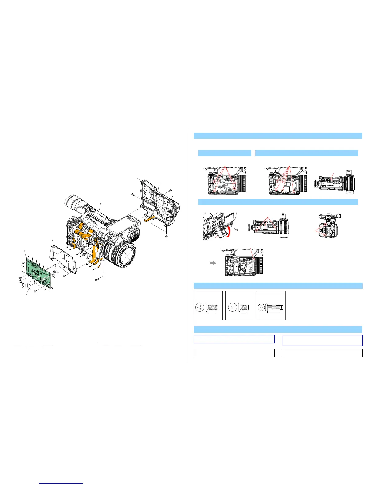
2-1-2. MAIN BOARD SECTION
Ref. No. Part No. Description
Ref. No. Part No. Description
51 A-1994-769-A VC-1020 BOARD, COMPLETE (SERVICE)
* 52 4-170-751-01 SPACER (A), VC
53 4-527-208-01 SHEET, VC COUNTERMEASURE (Note 2)
54 4-488-870-01 SHEET, VC RADIATION (Note 2)
55 4-527-210-01 SPACER (B), VC (Note 2)
* 56 4-165-252-01 FRAME, MAIN
#49 2-630-005-31 SCREW (M2), NEW TRUSTER, P2
#50 2-891-494-11 SCREW (M2), NEW TRUSTER, P2
#154 7-627-556-97 SCREW, PRECISION +P2.6X8 TYPE 1
1. Remove in numerical order (1 to 3) in the left figure.
DISASSEMBLY
1
#50 X 4
#50
Left View
3 Open Lid AL (3) → #49 X 6 → #154 X 1
3
#154
#49
Left View
Back View
#49
#49
Bottom ViewRight View
2
#49 X 6
Screw
#49: M2.0 X 4.0
(Black)
2-630-005-31
4.0
2.0
#50: M2.0 X 3.0
(Red)
2-891-494-11
3.0
2.0
8.0
2.6
#154: M2.6 X 8.0
(Silver)
7-627-556-97
(Note 2)
(Note 2)
(Note 2)
3
#50
#50
#50
#49
#154
#49
#49
#49
1
51
2
55
56
52
53
54
52
52
3 Cabinet (R) Section
(Note 1)
(See page 2-7)
Chassis Section
(See page 2-5)
F
E
D
C
L
K
J
H
G
I
B
A
I
L
H
K
G
M
N
M
N
A
B
C
D
E
F
J
#49
#49
Left View Bottom View
Note
Note 2: Do not reuse these Parts because their adhesive force
decreases when they are removed once.
Note 2:
これらの部品は一度剥がすと粘着力が弱くなるため、再利
用はしないでください。
Note 1: Refer to “Assembly-6: On installation of the Cabinet (R) sec-
tion, adjust the position of the ND filter switch” when installing.
Note 1:
組立時は“Assembly-6: On installationoftheCabinet(R)
section,adjustthepositionoftheNDfilterswitch”を参照し
てください。
 Loading...