– 15 – – 17 –– 16 –
ICF-1000L
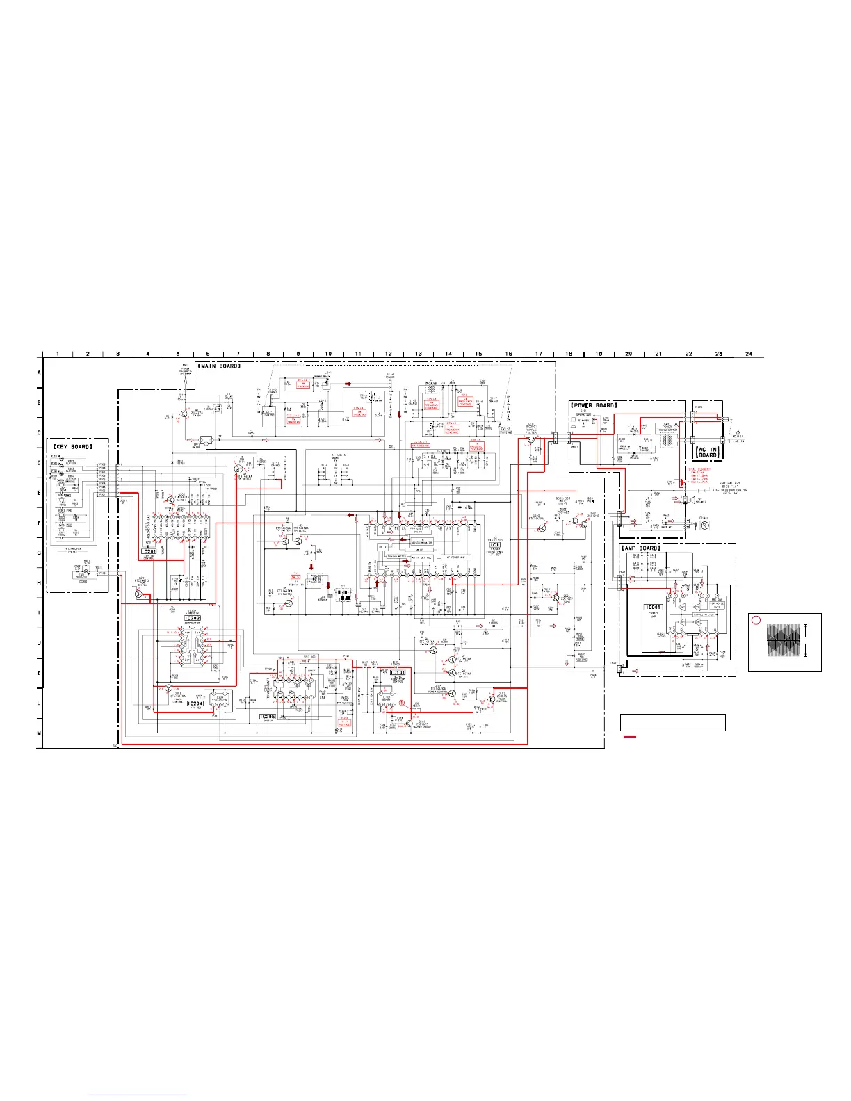
4-4. SCHEMATIC DIAGRAMS
Note:
• All capacitors are in µF unless otherwise noted. pF: µµF
50 WV or less are not indicated except for electrolytics
and tantalums.
• All resistors are in Ω and
1
/
4
W or less unless otherwise
specified.
•
f
: internal component.
Note: The components identified by mark 0 or dotted
line with mark 0 are critical for safety.
Replace only with part number specified.
• : B+ Line.
• H : adjustment for repair.
• Power voltage is dc 6 V and fed with regulated dc power
supply from battery terminal.
• Voltages and waveforms are dc with respect to ground
under no-signal (detuned) conditions.
no mark : FM
( ) : MW/LW/SW
• Voltages are taken with a VOM (Input impedance 10
MΩ).
Voltage variations may be noted due to normal produc-
tion tolerances.
• Waveforms are taken with a oscilloscope.
Voltage variations may be noted due to normal produc-
tion tolerances.
• Circled numbers refer to waveforms.
• Signal path.
F : FM
f : MW
z
Waveform
1
Q101 C
(Band : FM)
VOLT/DIV : 5 V AC
TIME/DIV : 1 msec
12 Vp-


 To Next Page