– 2 –
TABLE OF CONTENTS
Specifications ........................................................................... 1
1. GENERAL
Choosing Power Sources ................................................... 3
Operating the Radio Manual Tuning ................................. 3
2. DISASSEMBLY
2-1. Cabinet (Rear)............................................................. 4
2-2. Power Board ............................................................... 4
2-3. AC IN Board, AMP Board.......................................... 5
2-4. Main Board, Key Board.............................................. 5
2-5. Setting the Pointer ...................................................... 6
3. ELECTRICAL ADJUSTMENT
3-1. MW Section ................................................................ 7
3-2. LW Section ................................................................. 7
3-3. SW Section ................................................................. 7
3-4. FM Section ................................................................. 7
4. DIAGRAMS
4-1. Block Diagram............................................................ 9
4-2. Printed Wiring Boards (1/2) ......................................11
4-3. Printed Wiring Boards (2/2) ..................................... 13
4-4. Schematic Diagrams ................................................. 15
5. EXPLODED VIEWS
5-1. Rear Cabinet Section ................................................ 18
5-2. Front Cabinet Section ............................................... 19
5-3. Chassis Section ......................................................... 20
6. ELECTRICAL PARTS LIST................................... 21
SAFETY-RELATED COMPONENT WARNING!!
COMPONENTS IDENTIFIED BY MARK 0 OR DOTTED LINE
WITH MARK 0 ON THE SCHEMATIC DIAGRAMS AND IN
THE PARTS LIST ARE CRITICAL TO SAFE OPERATION.
REPLACE THESE COMPONENTS WITH SONY PARTS WHOSE
PART NUMBERS APPEAR AS SHOWN IN THIS MANUAL OR
IN SUPPLEMENTS PUBLISHED BY SONY.
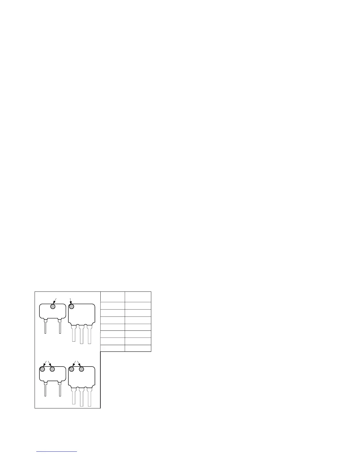
• HOW TO CHANGE THE CERAMIC FILTER
This model is used three ceramic filters of CF2, CF3 and CF4.
You must use same type of color marked ceramic filters in
order to meet same specifications.
Therefore, the ceramic filter must change three pieces together
since it's supply three pieces in package as a spare parts.
red
blue
orange
black
white
white/white
yellow
10.70MHz
10.67MHz
10.73MHz
10.64MHz
10.76MHz
10.75MHz
10.79MHz
Mark
Center
frequency
mark mark
• white/white only
CF2
CF3
CF4
markmark
CF3
CF2
CF4
Notes on chip component replacement
• Never reuse a disconnected chip component.
• Notice that the minus side of a tantalum capacitor may be
damaged by heat.