— 29 —
KV-21FA210
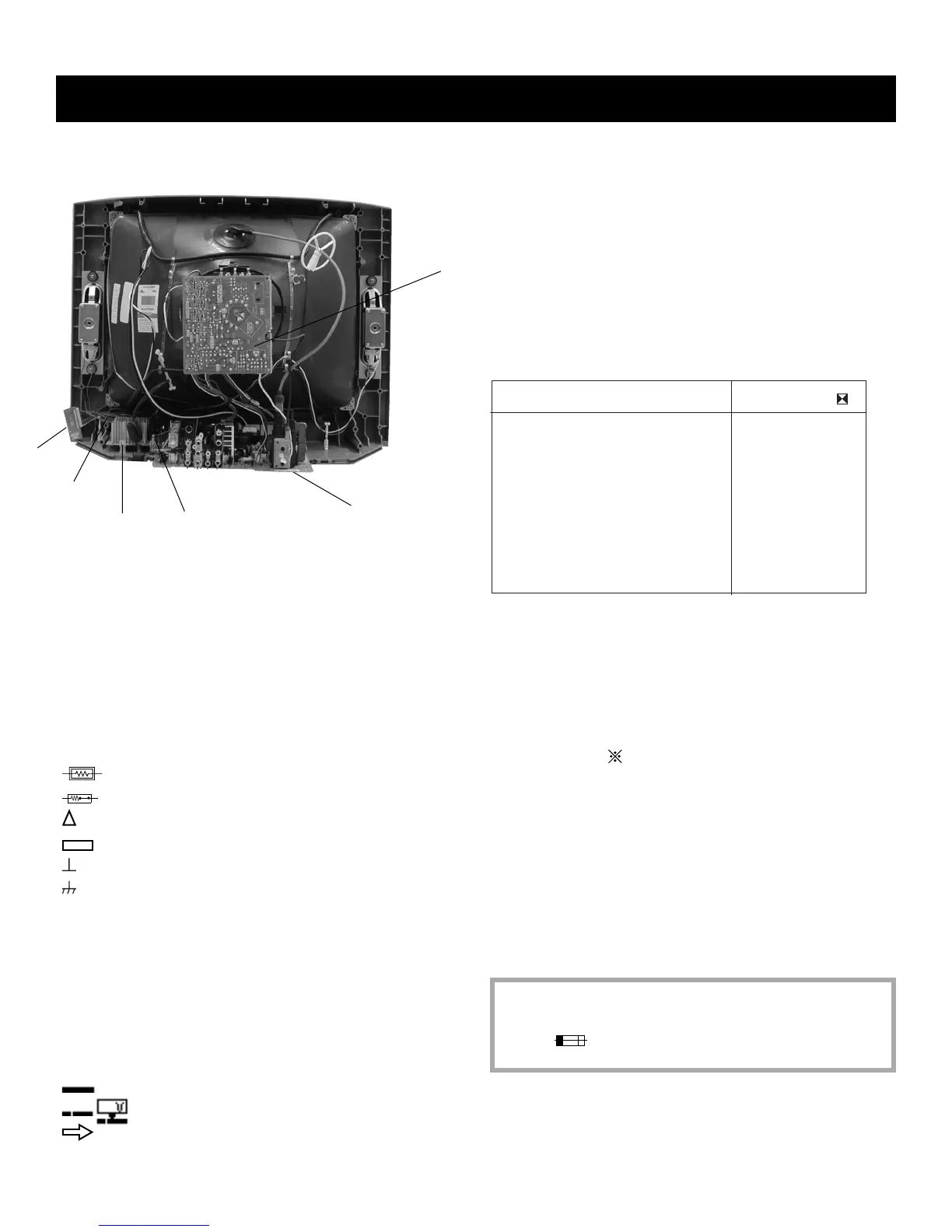
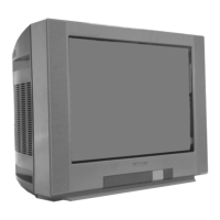
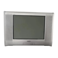
5-1. CIRCUIT BOARDS LOCATION
5-2. PRINTED WIRING BOARD AND
SCHEMATIC DIAGRAM INFORMATION
All capacitors are in µF unless otherwise noted. pF : µµF 50WV or less
are not indicated except for electrolytics and tantalums.
All electrolytics are in 50V unless otherwise specifi ed.
All resistors are in ohms. k=1000, M=1000k
Indication of resistance, which does not have one for rating electrical
power, is as follows: Pitch : 5mm Rating electrical power :
1
/
4
W in resistance,
1
/
10
W and
1
/
8
W in chip resistance.
: nonfl ammable resistor.
: fusible resistor.
: internal component.
: panel designation and adjustment for repair.
: earth ground
: earth-chassis
All variable and adjustable resistors have characteristic curve B, unless
otherwise noted.
Readings are taken with a color-bar signal input.
Readings are taken with a 10M digital multimeter.
Voltages are DC with respect to ground unless otherwise noted.
Voltage variations may be noted due to normal production tolerances.
All voltages are in V.
S : Measurement impossibillity.
: B+line.
: B-line. (Actual measured value may be different).
: signal path. (RF)
Circled numbers are waveform references.
The components identifi ed by shading and
!
symbol are critical for safety. Replace
only with part number specifi ed.
The symbol indicates a fast operating fuse and is displayed on the component
side of the board. Replace only with fuse of the same rating as marked.
The components identifi ed by
X
in this basic schematic diagram have
been carefully factory-selected for each set in order to satisfy regulations
regarding X-ray radiation. Should replacement be necessary, replace
only with the value originally used.
When replacing components identifi ed by
Y
, make the necessary
adjustments as indicated. If the results do not meet the specifi ed value,
change the component identifi ed by
X
and repeat the adjustment until
the specifi ed value is achieved. (Refer to Section 3: Safety Related
Adjustments on Page 15.)
When replacing the parts listed in the table below, it is important to
perform the related adjustments.
Part Replaced ( )
Adjustment ( )
DY, T585, CRT, IC001, IC561,
IC604, C507, C508, C506, T511,
L510, C588, L588, C566, C561,
C563, D567, D568, D566,
PH602, R567, R568, R565,
R566, R562, R563, R561, R528,
R668....................A Board
HV HOLD-DOWN
R565
REFERENCE INFORMATION
RESISTOR : RN METAL FILM
: RC SOLID
: FPRD NONFLAMMABLE CARBON
: FUSE NONFLAMMABLE FUSIBLE
: RW NONFLAMMABLE WIREWOUND
: RS NONFLAMMABLE METAL OXIDE
: RB NONFLAMMABLE CEMENT
: ADJUSTMENT RESISTOR
COIL : LF-8L MICRO INDUCTOR
CAPACITOR : TA TANTALUM
: PS STYROL
: PP POLYPROPYLENE
: PT MYLAR
: MPS METALIZED POLYESTER
: MPP METALIZED POLYPROPYLENE
: ALB BIPOLAR
: ALT HIGH TEMPERATURE
: ALR HIGH RIPPLE
SECTION 5: DIAGRAMS
A Board
CV Board
M3 Board
Y
K Board
HR Board
KB Board




 To Next Page