38
English
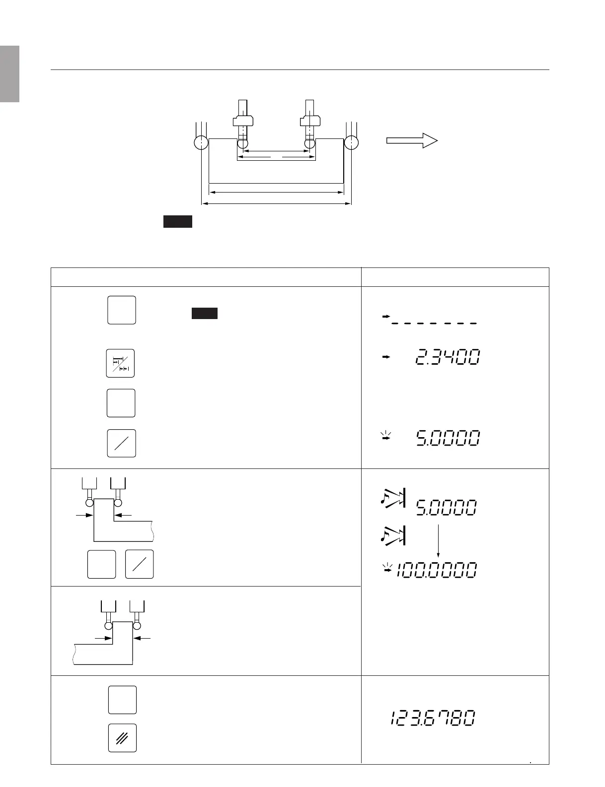
Inside and outside measurements of workpiece
Operating Procedure
Select the X-axis.
Note
If an axis is not selected, all axes are
switched simultaneously.
Set the incremental mode (INC).
(The spot position is displayed.)
The INC indicater lights.
Select the X-axis again.
Press the LOAD key. It is ready for setting the
datum point on the side A (side C).
The arrow indicater flashes.
Touch the side A (side C) with the feeler. On
contact the buzzer beeps and counting starts.
The arrow indicater goes out.
Before touching the side B (side D), select the
X-axis and press the HOLD key.
It is ready for finding L1 (L2).
The arrow indicater flashes.
Touch the side B (side D) of the workpiece
with the feeler.
The buzzer beeps and the displayed value is
held, which is the value L1 (L2).
The arrow indicater lights.
Select X-axis again and press the cancel key.
The hold is canceled and the display will show
the present value.
The arrow indicater goes out.
X
Display
‘direction
Direction of movementand polarity
L1=s1+10mm
L2=s2–10mm
Outside measurement
Inside measurement
Example: L1=100
The display below shows the inside measurement.
Note
Make following measurements in millimeter operation.
Press the in/mm selector key if necessary.
AB
s1
L1
L2
s2
CD
X
AC
CB
X
Buzzer
Flashes
Flashes
Counting starts
L
SET
mm
INC
INC
mm
Buzzer
H
START
X
INC
mm
mm
mm
ABS
mm
INC
INC



 To Next Page